Download
1 / 17
170 likes | 345 Views
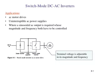
SW/HW Co-design Term Project Charge Pump System For DC/AC Conversion with Changeable Frequency. R92943074 胡以農 R92943061 詹作晟. Outline. System Block Diagram Charge Pump Circuit Oscillator Circuit Control Signal ADC Circuit Simulation Results Conclusion. System Block Diagram.

E N D
SW/HW Co-designTerm ProjectCharge Pump System For DC/AC Conversion with Changeable Frequency R92943074胡以農 R92943061詹作晟
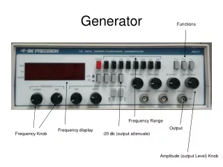
Outline • System Block Diagram • Charge Pump Circuit • Oscillator Circuit • Control Signal • ADC Circuit • Simulation Results • Conclusion
System Block Diagram DC Charge Pump 3.6 V 1.8 V Control Clock ADC Vdd Oscillator Clock AC Charge Pump 7.2 V
Analysis of The Charge Pump _ + 2Vin Charge phase Transfer phase
AC Output Voltage V1 4Vin Vo 4Vin 0 t V2 t t 4Vin -4Vin 0 t
Oscillator Circuit I VH L L H S Q VH L L H R VL f = I/2CV C V=(VH-VL) VL I
Control Signal Charge Pump Oscillator Cf ADC A Op Control signals 0000 0001 0011 0111 1111
Conclusion • Use more than one small capacitor in a chip to achieve the large driving current ability. • Use low voltage to produce a high voltage in order to drive a system.