Download
1 / 25
250 likes | 410 Views
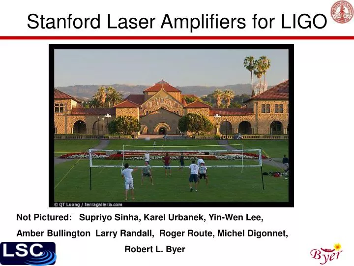
Stanford Laser Amplifiers for LIGO. Not Pictured: Supriyo Sinha, Karel Urbanek, Yin-Wen Lee, Amber Bullington Larry Randall, Roger Route, Michel Digonnet, Robert L. Byer. Status and Direction. LIGO box and amplifier sent to Hanford in ‘06

E N D
Stanford Laser Amplifiers for LIGO Not Pictured: Supriyo Sinha, Karel Urbanek, Yin-Wen Lee, Amber Bullington Larry Randall, Roger Route, Michel Digonnet, Robert L. Byer
Status and Direction • LIGO box and amplifier sent to Hanford in ‘06 • We needed a seed • Fibers at the focus • 10W amplifier designs • Ytterbium-doped silica fibers • Ytterbium-doped phosphate fibers • Continue work on LMA amplifiers • Ytterbium-doped Silica fibers • Erbium-ytterbium co-doped phosphate fibers • Slabs on hold • Ceramic Slabs?
Goals ~10 W of power Use only standard SMF All integrated source Convective cooling (no water!) Power fluctuations of +/- 2% over 40 s MTTF > 20000 hours Reliable, easy to use CHEAP! (<$10k) Otherwise we would have bought one from Nufern Thus-far Built first unit Over 10W out! >40% optical efficiency wrt output diode pump power Low power fluctuations <0.05% over 40 sec 82% through PMC 30 hour successful lifetime test (no photodarkening!) Burned at 31 hours of lifetime test In process of rebuild 10-W front end
Actual Layout Air-cooled pumps are removed from Laser table Silicate bonded flat Input Output Gain fiber
Pump Stripping Failure Site We still had enough residual pump to melt jacket
Silicate Bonding Silicate bonding Silicate bonding can be used to lower optical feedback Fresnel reflection measured to be below -63 dB Optical damage thresholds ~ 500 J/cm2 at 1 s
Collimating the signal • Relative position of fiber tip should be fixed w.r.t lens • Commercial holders for high power applications are rare, and holder usually heats up, resulting in pointing instability • We propose trial of optical bonding of aspheric lens to exit surface of optical flat • Must be able to coat the aspheric surface • We have investigated various aspheric lenses
Trouble with Aspheric Lenses All large diameter Aspheric lenses we tried introduced aberrations. After going through a focus, we consistently saw a “donut” mode. Material problem? Design needs to be specific?
Test Results for First System • Decent Slope efficiency,(~50%) but we are happy to sacrifice some pump light for stability • We did see SBS effects at fiber lengths longer than 4m, and output signal powers >6W • Observed RIN < 0.1% above 1Hz • Best fiber length ~3.7 meters A Bad Splice (way too common) A long term test was performed in which the fiber burned in the 31st hour. Subsequent splices failed (a good splice requires much luck) and we needed to order more gain fiber.
Some Results • Reflection dips from the PMC (10-year old) showed 97% of the light coupled in. • We were able to see stable locking, with 82% throughput • Fluctations < 1% above 1Hz 200us trace 40s trace Dark Current
What Now? • The High-Power fiber laser industry continues to move very fast • Very soon the following will be known • 20-W 100-µm-fiber-coupled wavelength-stabilized pumps will be available for about $2k • Temperature feedback control is unnecessary --- diodes can be fan cooled • 1 diode per 10-W system (the pump diode industry is also making progress) • Suitable high-power pump / signal combiners will be available for about $300
Build Your Own! • Cost of materials • Pump diode $2000 • Signal / Pump combiner 300 • Gain fiber 200 • Taps, monitor PD’s, polarizer 1000 • Electronics, diode driver 1000 • Assembly ? All in all, a 10W amplifier for less than $5k
Future System Proposal 30W integrated system uses only 3 pump diodes and simplified controls
High Power, Single Frequency Ytterbium Fiber Amplifier (Not quite ready for the commercial market)
Optical Layout (new) 136-W single-frequency, polarized fiber amplifier operating at 1064 nm Characterized noise properties of LMA fiber amplifier Drilled hole here to monitor pump
TEM00 FSR (b) High Power Fiber Amplifier Results M2 < 1.05 Analysis of mode cleaner reflection spectrum indicates that less than 1.5% of the output power is contained in the higher order modes at 10 W level 136 W of output power achieved with a PER of 15 dB but output power fluctuates by +/-10% on a ~30-second timescale due to periodic drift in the laser diode output spectrum.
LMA Fiber Amplifier Highlights • Gain fiber was kept very short to minimize spontaneous Brillouin scattering excess noise (side effect was that the output power is more sensitive to pump wavelength) • Long period output power fluctuations could be eliminated with wavelength-stabilized pumps or pumps with better cooling geometry that have minimal wavelength drift • Amplifier has been used on-and-off for months without degradation or failure • Used to set world record for diffraction-limited single-pass frequency doubling (19W of 532nm light)* * PPSLT provided by David Hum, Stanford University
150W System Layout All key components have now been developed (in house and/or commercially) over the last few years
Meet Yin-Wen Lee Built 10W and 25W single-mode Yb-doped Phosphate fiber amplifier and laser Working toward 100W class Yb-doped phosphate fiber laser sources leeyw@stanford.edu
Double-Clad Phosphate Fiber Fiber fabrication: • Rod-in tube technique • Eliminated the alkali ions 12 wt% of Yb2O3 3-dB/m passive loss • SBS gain co-efficient looks to be 2x lower than silica (2.34 e-11 m/W) • Photodarkening threshold appears to be orders of magnitude above silica
25-W Single-mode Yb3+-doped phosphate fiber lasers experimental data simulation curve Slope efficiency: 52.7% (launched pump power) 59.4 % (absorbed pump power) Slope efficiency: 25.8 % (launched pump power) 34.4 % (absorbed pump power) • The slope efficiency can be improved by pumping at 975 nm or decreasing the • passive propagation loss • The background propagating loss is mainly due to impurities of glass preforms
10-W Single-mode Yb3+-doped phosphate fiber MOPA • The pump absorption can be improved by breaking the symmetry of • the inner cladding, such as using a PM fiber • Our collaborators at NP photonics are making PM Yb3+ doped double- • clad single-mode fiber
Conclusions and Future Work • Built and began testing a successful 10-W fiber amplifier using a truly single-mode ytterbium-doped silica fiber • Continued to improve upon the high-power LMA silica fiber amplifier, increasing stability and beam quality • After 10W amplifier is rebuilt, we will be able to do a full characterization and long lifetime test. • We will begin construction on a 2nd-generation amplifier, consisting of only 1 fiber-coupled wavelength-stabilized diode source, fewer electronics, and a smaller footprint • A 100-W class phosphate fiber amplifier will be built and tested this coming year • We will find a suitable replacement for Supriyo • Note: Average winter temperature for Palo Alto: 11 deg. C • Average Summer temperature: 21 deg. C