Download

1 / 48
480 likes | 698 Views
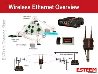
Wireless Serial Overview. Serial Over Broadband. Serial Interface on 195E products Serial Data Transferred Over Ethernet System Configure Ethernet links first Troubleshooting and diagnostic of WLAN network Serial Links are Transparent Two Modes of Operation Point to Point Multicast.

E N D
Serial Over Broadband • Serial Interface on 195E products • Serial Data Transferred Over Ethernet System • Configure Ethernet links first • Troubleshooting and diagnostic of WLAN network • Serial Links are Transparent • Two Modes of Operation • Point to Point • Multicast
Serial Interface Layout Second Ethernet Port RS-232 Configuration RS-232 Data Port RJ-45 10/100BaseT Ethernet Port Reset Switch Status LED Aux Power LED Receive LED 12 VDC Input (Auxiliary Connector ) Transmit LED Power over Ethernet LED
Serial Port Configuration • Single Page Configuration on Setup • Data Rate, Parity, Start/Stop Bits • Transmission Characters • Data Format • Multipoint System • All remote sites will receive the data • Set to multicast address • Separate Networks with Port Number
Serial and Ethernet Networks • Hybrid of Both Serial and Ethernet Interface • Both Serial and Ethernet Network Can Work Simultaneously • Legacy systems • Adding in new locations to existing site • Providing video link on serial network • Serial Network has Little Impact on Bandwidth
Theory Of Operation (Licensed) • Narrow Band Packet Burst • Single Narrow Band Radio Channel • Carrier Sensed Multiple Access (CSMA) • Listen before transmit • Multiple users on one frequency • Collision Detection • Fixed delay + random variable = time
Theory Of Operation (Licensed) • Networking • Single Frequency Channel • Model 192C/CHP/M/MHP/F • 1600 channels (12.5 kHz spacing) • 3200 channels (6.25 kHz spacing) • Up to 256 cells per channel • Network ID • Range 0 to 255 • 254 Users per cell • Unit Address • Range 1 to 254 per cell
Theory Of Operation (Licensed) • Spectrum Utilization • Multiple frequencies available in band • 20 kHz channel spacing in low band VHF • 12.5 kHz or 5 kHz channel spacing in high VHF • 25 kHz channel spacing - UHF (Grandfather) • 12.5 kHz channel spacing - UHF (Current) • 6.25 kHz channel spacing - UHF (?) • Simplex Radio • Only one channel needed per site
Theory Of Operation (Licensed) • Digi-Repeating • Store and Forward Data Transfer • Maximum of Three Repeaters in Any String • Acknowledge comes from destination ESTeem - not from first repeater
Digi-Repeating Diagram Add 30 Data 2nd Repeater Add 20 Data 1st Repeater 3rd Repeater Data Add 40 Data Source Add 10 Destination Add 50
Theory Of Operation (Licensed) • Error Detection • Forward Error Correction • Every 4th Bit is Error Correct • 32 Bit CRC • Retry
Noise Immunity • High EMF Noise Rejection • Narrow Band FM • CSMA-CD • Error Detection • Retry • Forward Error Correction • Receiver Squelch • Narrow receiver band • Four level squelch
Packet Protocols • Master/Master Communications • Any ESTeem can act as master • No dedicated Master/Slave relationship • Simplicity in maintaining spares • No Token Packets • Transmit only when data to send • Opens up radio spectrum for multiple users
Data Privacy • Network Privacy • Address • 1 to 254 • Network ID • 0 to 255 • Operating Frequencies • 1600 @ 12.5 kHz • 3200 @ 6.25 kHz
Data Privacy • Network Privacy • Programming Lockout Codes • Security ON/OFF • 0 to 65,536 • Data Rate • 51 • Embedded Subcode • Internal Firmware • 0 to 255 • Total Combinations to Access Data • 1 in 1.35 Trillion (1.35 E12)
Packet Frame Block Diagram Transmitted Frame Data 1 to 2000 Bytes (8 to 16000 Bits) 32 Bit CRC Polynomial Start Flags Destination Address Source Address Network Frame Overhead: 64 to 118 bits Start Of Transmission • Packlength Buffer Full • Sendpack Character Received • Termcontrol Timer Enabled and Timed Out End Of Transmission Acknowledge Frame 32 Bit CRC Polynomial Start Flags Destination Address Source Address Network
ESTeem Block Diagram TX BUFFERS TX BUFFERS TXB2 TXB1 TX TXB1 TX TXB2 TX BUFFER SIZE = PACKLENGTH T/R T/R TX BUFFER SIZE = PACKLENGTH USER DEVICE SERIAL INTERFACE SERIAL INTERFACE USER DEVICE RX RX BUFFER RX RX BUFFER RX BUFFER SIZE = 4000 BYTES RX BUFFER SIZE = 4000 BYTES ESTEEM INTERNAL BLOCK DIAGRAM ESTEEM INTERNAL BLOCK DIAGRAM
Serial Interface • DTE Vs. DCE • All ESTeem Wired DCE • Serial Flow Control • Software Flow Control • XON/XOFF in data stream • Hardware Flow Control • Assertion of RTS and CTS lines
Serial Interface ESTeem Personal All Models Computer 1 GROUND TXD 2 2 TXD RXD 3 3 RXD RTS 4 4 RTS CTS 5 5 CTS 6 6 DSR DSR SIG GND 7 7 SIG GND DCD 8 8 DCD NOTE: Connect only wires 25-Pin Male 25-Pin Male shown between pins. Connector Connector • RS-232C Interface • Standard DCE, RS-232C cabling • Maximum distance 50 feet (approx.)
Serial Interface • RS-422/485 Interface • Greater Distances (up to 4000 feet) • RS-485 for Multi-drop Serial Connections RS-422/485 Connection ESTeem All Models ESTeem All Models Two Wire RS-485 Connection 1 SHIELD GND 1 SHIELD GND + 14 TX + Pos TX + 9 + - Pos TX - TX - 16 10 Neg - RX + Neg RX + 14 RX - - 16 RX 25-Pin Male Connector Connect only wires shown between pins 25-Pin Male Connector
Communication Interfaces • Infrared Port (Model 192) • No Physical Connection Required • Serial Port Converter - Dongle • ESTeem AA300 • 3 Foot Range
Effective Baud Rate • Effective Baud Rate • Transmitter Turn On Time • Packet Overhead • Total of 15 ms (Model 192) • Effective Baud Rate Table • Applicable to file transfer • Effected by number of repeaters and size of packets
Calculating Polling Time • Packet Overhead • 15ms + Data (Bits)/19.2k Baud Each Transmission • Total Packet Turn Around Time • 15ms+Data/19.2k+15ms (Ack) • Retry = 50ms
Calculating Polling Time • Polling Time • Number of transmission in message plus overhead • Average retry rate
Polling Time Example • Typical Read Message (10 Words) • Header • 15ms+Data/19200 Baud = 23ms • Ack to Header • 15ms • Read • 15ms+Data/19200 Baud = 23ms • Ack to Read • 15ms • Conservative Estimate • Maximum of ten polls per second
Communication Schemes • Point to Point • Two ESTeem network • Simple configuration
Communication Schemes • Contention • Priority Messages Have Quickest Response • Possible Unknown Communication Loss at Remotes Master Remotes
Communication Schemes • Polled • Well Organized Communication • Priority Messages Wait on The Poll Master Remotes
Communication Schemes Emergency Message • Polled With Report By Exception • Combines the Advantages of Polled and Contention • Must Add Small Delay After Poll Master Remotes
Licensing • Bringing Order to Frequency Spectrum Chaos • Costs and File Times Depend on Coordinators Fees • Licensing Assistance Offices • Approx. 6-8 Weeks for new license return from coordinator (temporary use) • Approx. $700-$1100 • Interim License As Fast As 4-6 Weeks
Install ESTeem Utility Software • Windows™ Based • Setup • Diagnostic Programs • Programming • PC Terminal Emulation • Full Documentation
ESTeem Utility (Windows) • Located on ESTeem Resource CD • Auto-run Menu • Select ESTeem Utilities • Open Zip File to Install
Interfacing ESTeem to PC ESTeem Modem Personal Computer RS-232 Cable
Power Supply Setup • 11-15 VDC Input - All Models • Molex Power Connectors ESTeem Modem Power Supply AA174 Molex Power Cord Female Molex Power Cord Male
Connecting Antenna • Connect Coax Cable to Antenna Port on ESTeem • Connect Antenna Element to Base Magnetic Base Antenna Unit Mount Antenna
Powering Up The ESTeem • Place DC connector to ESTeem • No On/Off Switch • Indications • Power LED = ON • Terminal Emulation • Welcome Message • Command Prompt (CMD:) • Modem Found on Starting Out ESTeem Modem Power LED
Using Infrared Port • 9,600 Baud Only • 3 Foot Range • ESTeem Dongle - AA300 • Initialized with ESTeem Utility • Alt-I on keyboard • Defaults Command Mode when Switch 8 (RS-232 Connector) = On • Must type Ctrl-C for Command Prompt
ESTeem Setup • ESTeem Setup Guide • Familiarize Yourself With ESTeem Operations • Basic Programming and Description • Programming Wizard Format • Express Setup • ESTeem Programming Without Descriptions • Test Communications • Modem to Modem • Loopback
ESTeem Diagnostics • Measure Receive Signal Strength • Radio Interference Testing • Measure Data Quality • Polling Diagnostic Testing • Save Results to File • Read and Print Test Results
ESTeem Programming • Configure Modes and Features • All Programming Commands In Users Manual In This Section • Building An ESTeem Command List • PLC Emulation Configuration • Saving Program • Reading Program • Remote Programming
Terminal Emulation • Direct Communication with ESTeem • Manual Programming and Communication • Setting Frequency and Squelch • Finding Frequency and Squelch of attached ESTeem • Function Keys • Custom Programming • Diagnostics
Additional Information • All ESTeem Documentation Contained on CD-ROM Disk • Manuals • Technical Bulletins • Engineering Reports • About • Lists current Utility version