Download
1 / 14
150 likes | 368 Views
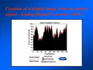
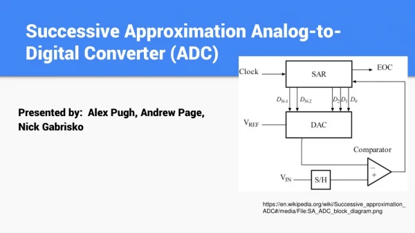
Analog-to-Digital Converter (ADC). ADC Features (1/3). ADC conversion rate 1 MHz and 12-bit resolution 1µs conversion time at 56 MHz 1.17µs conversion time at 72 MHz Conversion range: 0 to 3.6 V ADC supply requirement: 2.4V to 3.6 V

E N D
ADC Features (1/3) • ADC conversion rate 1 MHz and 12-bit resolution • 1µs conversion time at 56 MHz • 1.17µs conversion time at 72 MHz • Conversion range: 0 to 3.6 V • ADC supply requirement: 2.4V to 3.6 V • ADC input range: VREF- ≤ VIN ≤ VREF+ (VREF+ and VREF- available only in LQFP100 package) • Dual mode (on devices with 2 ADCs): 8 conversion mode • Up to 18 multiplexed channels: • 16 external channels • 2 internal channels: connected to Temperature sensor and internal reference voltage (VREFINT = 1.2V)
ADC Features (2/3) • Channels conversion groups: • Up to 16 channels regular group • Up to 4 channels injected group • Single and continuous conversion modes • Sequencer-based scan mode for up to 16 conversion • External trigger option for both regular and injected conversion • Channel by channel programmable sampling time • Discontinuous mode on regular and injected groups • Self-calibration
ADC Features (3/3) • Left or right Data alignment with inbuilt data coherency • Analog Watchdog on high and low thresholds • Interrupt generation on: • End of Conversion • End of Injected conversion • Analog watchdog • DMA capability (only on ADC1)
ADC Block Diagram VREF+ VREF- VDDA PCLK2 ADCCLK VSSA ADC Prescalers: Div2, Div4, Div6 and Div8 GPIO Ports ADC_IN0 ADC DMA Request Address/data bus ADC_IN1 Up to 4 . . . Injected Channels Injected data registers (4x12bits) ANALOG MUX ADC_IN15 Up to 16 Regular Channels Regular data register (12bits) Temp Sensor End of injected conversion VREFINT End of conversion Analog Watchdog TIM1_TRGO Analog watchdog event Start Trigger (injected group) TIM1_CC4 High Threshold register (12bits) TIM1_TRGO TIM2_CC1 TIM3_CC4 JEXTRIG bit Low Threshold register (12bits) TIM4_TRGO AWD EOC JEOC Flags Ext_IT_15 JEXTSEL[2:0] bits Interrupt enable bits AWDIE EOCIE JEOCIE TIM1_CC1 TIM1_CC2 TIM1_CC3 Start Trigger (regular group) TIM2_CC2 TIM3_TRGO ADC interrupt to NVIC EXTRIG bit TIM4_CC4 Ext_IT_11 EXTSEL[2:0] bits
ADC Regular channels group • Programmable number of regular channels: Up to 16 channels • Programmable sample time and conversion sequence • Conversion started by: • Software through start bit • External trigger generated by: • Timer1 CC1 • Timer1 CC2 • Timer1 CC3 • Timer2 CC2 • Timer3 TRGO • Timer4 CC4 • EXTI Line11
ADC Injected channels group • Programmable number of injected channels: Up to 4 channels • Programmable sample time and conversion sequence • Conversion started by: • JAUTO: automatic injected conversion after regular channels conversion • Software through start bit • External trigger generated by: • Timer1 TRGO • Timer1 CC4 • Timer2 TRGO • Timer2 CC1 • Timer3 CC4 • Timer4 TRGO • EXTI Line15
Analog sample time • ADCCLK, up to 14MHz, taken from PCLK2 through a prescaler (Div2, Div4, Div6 and Div8) • Three bits programmable sample time cycles for each channel: • 1.5 cycles • 7.5 cycles • 13.5 cycles • 28.5 cycles • 41.5 cycles • 55.5 cycles • 71.5 cycles • 239.5 cycles ADC 1.5 cycles 7.5 cycles 13.5 cycles PCLK2 28.5 cycles ADCCLK ADC Prescalers: Div2, Div4, Div6 and Div8 Sample Time Selection 41.5 cycles 55.5 cycles 71.5 cycles 239.5 cycles SMPx[2:0]
Sequencer • Sequencer: different order, different sampling time and oversampling possibility. Example: - Conversion of channels: 1, 2, 8, 4, 7, 3 and 11 - Different sampling time. - Oversampling of channel 7. Channel1 Channel2 Channel8 Channel4 Channel7 Channel7 Channel7 Channel3 Channel11 71.5 cycles 7.5 cycles 7.5 cycles 1.5 cycles 1.5 cycles 13.5 cycles 28.5 cycles
ADC conversion modes • Four conversion mode are available: Start Start CHx CHx Start Start Stop Single channel continuous conversion mode CHx CHx Single channel single conversion mode . . . . . . CHn CHn Stop Multi-channels (Scan) continuous conversion mode Multi-channels (Scan) single conversion mode
ADC Analog Watchdogs • 12-bit programmable analog watchdog low and high thresholds • Enabled on one, some or all converted channels: one regular or/and injected channel, all injected or/and regular channels. • Interrupt generation on low or high thresholds detection ADC_IN0 ADC_IN1 Analog Watchdog AWD . . . Low Threshold Status Register High Threshold ADC_IN15 Temp Sensor VREFINT
ADC dual modes • Available in devices with two ADCs: ADC1 master and ADC2 slave • ADC1 and ADC2 triggers are synchronized internally for regular and injected channels conversion ADC_IN15 ADC_IN1 ADC_IN0 … Temp Sensor GPIO Ports VREFINT … ANALOG MUX Up to 16 regular channels Up to 4 injected channels ADC1 Analog ADC2 Analog External event (Regular group) External event synchronization Digital Master Digital Slave Data register External event (Injected group) EOC/JEOC
Now you are able to… Develop your application around STM32F10x device