Download
1 / 20
200 likes | 354 Views
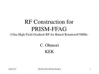
FFAG RF - A new type of RF cavity for spiral FFAG -. C. Ohmori, KEK. First beam at 3NBT Dump. From Dr. Meigo, 1e11ppp. Sector FFAG. Shape of straight section fits RF cavity. Assuming 50 cm for RF cavity, 6 kV 100%duty seams possible using direct water cooling MA cavity.

E N D
FFAG RF- A new type of RF cavity for spiral FFAG - C. Ohmori, KEK
Sector FFAG • Shape of straight section fits RF cavity. • Assuming 50 cm for RF cavity, 6 kV 100%duty seams possible using direct water cooling MA cavity. • But, for spiral FFAG the curved shape of straight section does not fit RF cavity.
Power Consumption for FFAG cavity • 10MeV->140 MeV • 1.5->4 MHz • 6 kV/gap, 100 % duty • 4 X PRISM-size cores • 1.7 m X 1m X 3cm • Size of Cavity :2m X 1.2 m X 0.4-0.5 m • 45 kW/gap, 11.25 kW/core • 0.32W/cc (av.), 0.54 W/cc (Max.) < 1 W/cc
It does not fit in a straight section although it has 50 cm length. If we put water tanks separately, it may fit. But, still very close to magnet. Need to estimate the magnetic field effect on MA cores.
New type of RF cavity • Drift tube in beam pipe which connected to tuning cavity and amplifier which are located beside the beam pipe. • Potential of drift tube varies according to tuning cavity voltage. • Drift tube through the FFAG magnets and covers >1/6 of circumference. • Core can be located apart from magnets. Less effect on MA cores by magnets.
Drift tube type cavity MA cavity - - p - + + p + p RF
Drift Tube type cavity • Similar to FNAL booster cavity • Two gap cavity • Drift tube crosses DC magnetic field. • Length of drift tube is 1/6-1/2 of circumference. • V=V0 for 1/6, V=1.4V0 for 1/4, V=2V0 for 1/2 • Shape of acceleration gap can be curved to fit the beam orbit. • Tube and beam pipe makes a large capacitance. It may reduce the cavity impedance.
Schematic diagram Mag Mag Mag Mag Push-pull Amplifier MA cavity (LEIR type cavity)
Drift tube type cavity for spiral FFAG Large capacitance may cause the impedance reduction as it move the resonance frequency lower. AMP cavity
Dual Drift tube type cavity Two short drift tubes. Does not reduce aperture in magnets and less capacitance on drift tubes. Assuming magnet and drift space have same length. cavity AMP V=V0(Sin 3/16-sin/16+sin-16-sin-3/16) =0.72 V0 More precise engineering design is needed to increase effective RF voltage.
LEIR RFSYSTEM – RING SECTION 4kV/cavity 0.7MHz-5 MHz From M. Paoluzzi
LEIR RF SYSTEMCavity Model: Half-Cavity Z (1, 2 and 3 Cores) -At low frequency impedance proportional to the number of cores. -At high frequency peak moves down because of the increased inductance.
LEIR RF SYSTEMCavity Model: Half Cavity Z (1 Core ) Additional C: 0 +20pF +40pF +100pF Response similar to that of an RC circuit. Above cutoff the slope is mainly dependent on C value. Structure capacitance is ~12pF.
Additional inductor • As another knob to tune a cavity, additional inductor in parallel to cavity may work to resonate at higher frequency. • But, it will increase effective Q-value. Bandwidth will be narrower.
Summary • Two solutions for spiral FFAG • Cavity with large cores • Effect by Magnetic field • Production process of core and coating need to be controlled well. • Cost of cores are not cheep. • If about 50 cm space is available, 6 kV RF voltage. • drift tubes and small cavity • Capacitance effect will reduce the impedance. Need to estimate or to make a cold model. • A design for CERN-LEIR RF system can be used for design. • Effective RF voltage will be 4 kV X 0.72 =3 kV