Download

1 / 40
400 likes | 733 Views
TRUE OCCUPANCY SENSORS. BY TERRY WEI CHENGYU ZHANG DEBOJIT NAYAK. INSPIRATION FOR OUR PROJECT. WHAT IS OUR PROJECT IS ABOUT. Automated detection of number of people in a room Automated control of lighting system within a room

E N D
TRUE OCCUPANCY SENSORS BY TERRY WEI CHENGYU ZHANG DEBOJIT NAYAK
WHAT IS OUR PROJECT IS ABOUT • Automated detection of number of people in a room • Automated control of lighting system within a room • Prototype for implementation in large scale office building and campus classrooms
ADVANTAGES AND BENEFITS • Conserve energy sources • Reduce unnecessary costs • Computer monitoring system • Improve decision-making abilities • Such as lighting and temperature controls
PRODUCT COMPONENTS • Passive Infrared Sensor (PIR) • Voltage Regulator • Peripheral Interface Controller (PIC) • Transmitter • Receiver • Computer Display (RS-232) • Relay
Passive Infrared Sensor Data PIC Microcontroller Relays (Lighting System) RS-232 (PC) DESIGN IMPLEMENTATION Wireless Transmission
OVERALL STRUCTURE Transmitter Counting sensor 1 Transmitter Counting sensor 2 Transmitter Motion sensor 1 Transmitter Motion sensor 2 Receiver1 Receiver2 3 Receiver3 4 Receiver4 1 2 All circuits are powered by 9V battery via a 5 V voltage regulator.
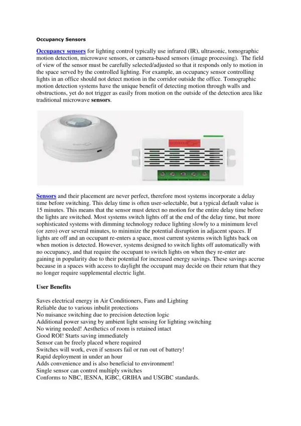
PASSIVE INFRARED SENSORS • Passive Infrared Sensor: • Parallax Inc., 555-28027ND PIR Sensor • Features: • Output: Single Bit • Output Voltage (High): 3.2 Volts • Output Voltage (Low): 0.0 Volts • Operational Voltage: 3.3 Volts and 5.0 Volts • Current Drawn: < 100 mA • Sensitivity: • Range (Distance): Approximately 20 Feet • Range (Angle): 120°by 70° • Design: Responds to Sudden Changes • Calibration: • Requires ‘warm-up’ time due to settling time involved in ‘learning’ its environment • Time Required: 30 Seconds Figure 1. Image of Passive Infrared Sensor
PASSIVE INFRARED SENSORS Figure 3. Output of Passive Infrared Sensor with Motion from Figure 2 Figure 2. Diagram Displaying How Passive Infrared Sensor Detects Motion
PASSIVE INFRARED SENSORS • Triggering time is extremely important • Detecting movement at 80 milliseconds (Triggering Time) • Too fast • Double detection – senses one person twice • Detecting movement at 3 seconds (Triggering Time) • Too slow • Multiple people will enter or exit without being detected • Optimal detection time is approximately one second (Triggering Time) • Various tests on timing how long it takes for a person to pass through the sensing system
EXPLAINATION OF TRIGGERING TIME • TX = Triggering Time (Default Value: 3.4 second) • TX = 24576 * R10 * C6 • R10 = Resistor Value (Default Value: 200 kΩ) – Variable Value • C6 = Capacitance Value (Default Value: 0.24 nF) – Fixed Value • If TX is desired to be one second • New R10 Value is 30 kΩ • Resistor on sensor falls off when repeatedly changing triggering time, which causes sensor to be destroyed
PASSIVE INFRARED SENSORS • Output from Oscilloscope: Default 200kΩ Resistor
PASSIVE INFRARED SENSORS • Output from Oscilloscope: Attached 900Ω Resistor
VOLTAGE REGULATOR • Voltage Regulator: • National Semiconductor LM78M05CT • 3 Terminal Positive Voltage Regulator • Features: • Output Current: Excess of 0.5 A • Output Voltage: 5 Volts • Internal thermal overload protection • Peak Current Output: 700 mA
VOLTAGE REGULATOR • Schematic: 9V 5V 10 uF 1 uF Capacitor values were chosen to reduce ripple voltages – the larger the capacitance the better.
9-Volt Battery Input Voltage Regulator Passive Infrared Sensors LINX Transmitter Output Voltage (5 Volts) Output Voltage (5 Volts) Sensor Data VOLTAGE REGULATOR • Block Diagram:
RF MODULE (TRANSMITTER) Used Four Different Frequencies for Each of the PIR Sensors Source: Project 9 Presentation
RF MODULE (RECEIVER) Used Four Different Frequencies for Each of the PIR Sensors Source: Project 9 Presentation
RF MODULE Testing RF Module Transmitter Input: Sine Wave Receiver Output: Square Wave (Indicating 1 and 0 or High and Low)
RF MODULE Testing RF Module Transmitter Input: Signal from PIR Sensor Receiver Output: Delayed Reception
RS-232 (PC CONNECTION) • MAX232 • Converts signal from RS-232 serial port to signal suitable for using in the microchip
RS-232 (PC CONNECTION) • RS-232 • Cable Connection • C++ Application • Created using standard Windows libraries
MICROCONTROLLER (counting) PIR1 on? PIR1 on? NO NO YES YES PIR2 on? PIR2 on? NO NO BOTH on? BOTH on? IN/OUT? +1&PIR off -1&PIR off
MICROCONTROLLER (motion) Lights off in 20s PIR3 on? Lights on Lights off in 20s & Blink for 5s before turn off NO NO YES YES PIR4 on? NO NO YES YES Counter >0? Counter >0?
RELAYS Small size for high density PC board mounting Ideal for appliance, office equipment. PIC Output
ADDITIONAL FUNCTIONAL TESTS • Displaying Count Results
ADDITIONAL FUNCTIONAL TESTS • Ultrasonic Sensor Testing Time = 1.160 ms Distance from sensor to object = 20 cm
ADDITIONAL FUNCTIONAL TESTS • Ultrasonic Sensor Testing Time = 4.240 ms Distance from sensor to object = 73 cm
ADDITIONAL FUNCTIONAL TESTS • Ultrasonic Sensors • Not used due to limitation of range of detection (4 meters) • Can be easily ignored if something is in the way of ultrasonic sensor
SPECIAL SCENARIOS • Student hides under the table (or falls asleep) • Blinking system • Person enters in half way and decides to leave (or exits) • Causes false triggering of some entering • Carrying cardboard over one’s head • No detection or sensing • Bird enters room • Triggers room lights on • Throwing a hot dog into the room • Causes counting system to count
SPECIAL SCENARIOS • If count is zero and movement in room • Triggers room lights on • Turning on lights and counting system are independent • Turning off lights and counting system are dependent (blinking) • Fan blowing air • Does not detect or sense • Material of clothes • Still sense people walking in and out
SUCCESSES • PIC integration with passive infrared sensors • Receiving data from passive infrared sensors • Robust wireless transmission between passive infrared sensors and PIC • PIC analysis of passive infrared sensors to accurately keep count of number of people in room • PIC integration with RS-232 system • Data is correctly displayed on the PC • PIC integration with relays • Correctly controls the lighting system of the room based on sensor outputs
CHALLENGES • PIC programming • Learning to program PIC and interrupts • Integrating and communicating data between PIC and RS-232 (PC) • Understanding how to receive data on PC • Integrating counting system with room sensors • Finding a logical connection between two systems • Accounting for extreme situations (particular cases) • Explained on previous slides • Designing printed circuit boards • Learning to use the Eagle Layout Editor • Soldering
RECOMMENDATIONS (NEXT STEPS) • Use one receiver and sweep the desired frequencies to reduce hardware • Improve algorithm to integrate counting system with the room sensors • Add more sensors to enable a more robust algorithm for room detection and counting system • Implement the system on a full scale classroom with multiple quadrants • Integrate ultrasonic sensors with passive infrared sensors
CREDITS • Professor: Professor Carney • Teaching Assistant: Paul Rancouret • Teaching Assistant: Kieran Levin • Teaching Assistant: Jay Rappert • PCB Production: Mark Smart • Door Overhead Design: ECE Machine Shop • Essential Hardware: ECE Parts Shop