Download
1 / 47
490 likes | 643 Views
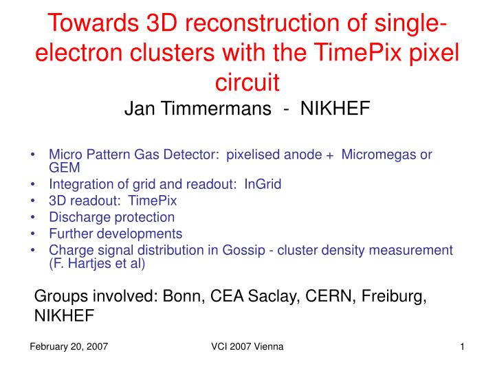
Towards 3D reconstruction of single-electron clusters with the TimePix pixel circuit Jan Timmermans - NIKHEF. Micro Pattern Gas Detector: pixelised anode + Micromegas or GEM Integration of grid and readout: InGrid 3D readout: TimePix Discharge protection Further developments

E N D
Towards 3D reconstruction of single-electron clusters with the TimePix pixel circuitJan Timmermans - NIKHEF • Micro Pattern Gas Detector: pixelised anode + Micromegas or GEM • Integration of grid and readout: InGrid • 3D readout: TimePix • Discharge protection • Further developments • Charge signal distribution in Gossip - cluster density measurement (F. Hartjes et al) Groups involved: Bonn, CEA Saclay, CERN, Freiburg, NIKHEF VCI 2007 Vienna
Goals • Gas multiplication GEM or Micromegas foil(s) • Charge collection with granularity matching primary ionisation cluster spread (this needs sufficiently low diffusion gas) • Investigate measurement dE/dx using cluster counting • 2D “proof of principle” based on existing Medipix2 readout chip: achieved 2004/05 • Add 3rd coordinate: Medipix2 TimePix: available; first results now • Integrate grid with pixel chip: InGrid: some results 2005/06 VCI 2007 Vienna
Micro Patterned Gaseous Detectors GEM • High field created by Gas Gain Grids • Most popular: GEM & Micromegas Micromegas Use ‘naked’ CMOS pixel readout chip as anode
Results pixel readout gas detectors NIKHEF-Saclay-CERN-Twente 55x55 μm2 pixels Ar/isobutane 95/5 VCI 2004: NIMA535 (2004)506 Also Bellazzini et al NIMA535(2004)477 δ ray Observation of min. ionising cosmic muons: high spatial resolution + individual cluster counting ! NIM A540 (2005) 295 (physics/0409048)
Freiburg Bonn Testbeam at DESY: 3-GEM+Medipix two tracks, d<1mm hard electron Si telescope (~20 μm precision) Lots of data being analyzed Still the same Medipix chip as 1.5 years ago Testbeam with Timepix in same setup VCI 2007 Vienna
‘GEM’ ‘Micromegas’ InGrid Integrate GEM/Micromegas and pixel sensor By ‘wafer post processing’ 4” wafer 19 different fields of 15 mm Ø 2 bonding pads / fields VCI 2007 Vienna
NIKHEF/Twente: InGrid (Integrated Grid) Deposit SU-8 Deposit anode UV exposure Deposit metal Pattern metal Develop resist VCI 2007 Vienna
Any field structure feasible VCI 2007 Vienna
Gain for different gap sizes(many other measurements in backup slides) Maximum predicted in gain vs gap curve d gap thickness p pressure A,B depend on gasmixture VCI 2007 Vienna
TimePix(EUDET: Bonn,Freiburg, Saclay, CERN, NIKHEF) • Distribute clock to full 256x256 pixel matrix • (50-100-160MHz) • Enable counting by first hit after ‘shutter’ opens, until ‘shutter’ closes (common stop); also time-over-threshold possible • Dynamic range 214 x 10 ns = 160 μs • (for the time being) no zero-suppress • to remain fullycompatible with Medipix2 • Shaping time ~200 ns • Keep same chip-size, pixel-size, readout • protocol • 1st full reticle submit done July 2006; • IT WORKS! See X. Llopart talk on Thursday
TimePix Test Beam Results(TimePix + GEM setup) • Point resolution from a straight line fit averaged over all drift volume of 6mm: 39.3 ± 1.3 μm for Ar/CO2 • Resolution near the first GEM (selected by Si- telescope and using the parametrisation of σ2): • 25.0 ± 2 μm for Ar/CO2 • 30.0 ± 2 μm for HeCO2 See poster PA25 – A. Bamberger VCI 2007 Vienna
Mixed Mode operation • Consecutive pixels have Time and TOT assignment and are here separated via mapping onto a 181x181 matrix • Benefit from charge & time information • Interesting for double track separation Ar CO2 70/30 He CO2 70/30 Freiburg Bonn VCI 2007 Vienna
First tracks with TimePix+SiProt+Micromegas: cosmics + α particle V_grid= -400 V; gain ~5000 He/Isobutane 80/20 Acquisition (‘shutter’) time ~ 1sec Time_over_threshold mode VCI 2007 Vienna
And triggered cosmics (sum of several triggers) Shutter time = 15 μs TimePix chip stayed alive for 40 days with He/isobutane And ‘died’ on 26/1/07 after 1.5 day with Ar/isobutane 80/20 VCI 2007 Vienna
3D reconstructed tracks in He isobutane 80/20 VCI 2007 Vienna
10μm Sparking • Chip faces 80kV/cm with no protection (unlike the GEM setup; 1.5 yr using same Medipix2 chip) (but now also one Timepix died in GEM setup) • Degradation of the field, or total destruction of grid but also CMOS chip VCI 2007 Vienna
CMOS Chip protection against - discharges - sparks - HV breakdowns - too large signals Silicon Protection: SiProt Amorph Si (segmented) Empirical method: Try RPC technology VCI 2007 Vienna
plasma A-Si - - - - • RPC principle: reduction of local E-field • Avalanche charge: electrostatic induction towards input pad • Specific resistance: - high enough to ‘block’ avalanche charge • - low enough to flow signal current • - layer thickness 4 μm, Rvol = 0.2 GΩ.cm Technology A-Si:H deposit possible in general; avoid wafers get too hot Univ. of Neuchatel/IMT/P. Jarron (CERN) uses this for integrated X-ray sensor/convertor on MediPix 2 Test: put Thorium in gas: Radon α-decays: - large (proportional) signals - Discharges: like short circuits VCI 2007 Vienna
current pulses Gain Iron 55 source Look at the pulses from a pre amplifier (low grid voltage) Look at the current flowing through the power supply (high grid voltage) No sparks up to 570 V on the grid ! Burn the grid above 570…
TwinGrid Alternative: VCI 2007 Vienna
Further Developments • Chip tiling: large(r) detector surfaces (2x2, 2x4 chips) • Through Si connectivity: avoiding bonding wires • Fast readout technology (~5 Gb/s) • Intermediate size TPC • Endplate module for LP • Octal chip board: 56 mm x 110 mm 12-layer pcb VCI 2007 Vienna
90Sr source 17 Collimator DAQ board Gossip Ø 0.6 11 PM 3 F. Hartjes et al GOSSIP 10 chamber used for cluster density measurements • Drift volume 13 x 13 mm, 1.24 +/- 0.01 mm high • Short charge collection path • Often inefficiency for mips (gas dependent) • => cluster density measurement • Signal electrode: large aluminium pad on silicon substrate • Micromegas has circular pads on 60 µm pitch • Closed gas volume of 210 µl
Pedestal peak Poisson convoluted with Pólya gain distribution and electronic noise
Cluster density calculation • Derive cluster density from amount of pedestal events • assuming a Poisson distribution • where x is the cluster density, f is the pedestal fraction and D is the width of the gas gap • But measured pedestal has contribution of Bremsstrahlung from characterisation station. Corrected for.
Literature Cluster density Kr/DME 74/26: 40.2 cm-1 Example • Gas: Kr/DME 74/26 • Measured histogram with fitted convoluted Poisson • Cluster density calculated from two independent methods • Magnitude pedestal peak • 2.55 +/- 0.07 % pedestal events • => cluster density 39.1+/-0.8 cm-1 • Fitting convoluted Poisson to experimental data • Using pdf =1 the best fit occurs at 38.2 +/- 2.6 cm-1¥ ¥Note that this number depends on the pdf value
Results so far * A.Pansky, G. Malamud, A. Breskin and R. Chechik: Applications of gaseous electron counting detectors, Nucl. Instr. and Meth. In Phys. Res. A323 (1992), 294. ¥ Using the expression in section 3.1 of I.B. Smirnov: Modeling of ionization produced by fast charged particles in gases, Nucl. Instr. and Meth. In Phys. Res. A554 (2005), 474.
Backup slides VCI 2007 Vienna
(β source) (from Freiburg GEM+Medipix setup - Andreas Bamberger) Triple GEM Total gain ~60k ~ 50 μm resolution Difference between Micromegas and GEM setup understood (simulation Michael Hauschild/CERN) VCI 2007 Vienna
Institute of Physics, Albert-Ludwigs-Universität Freiburg GEM-TimePix Project • Micro Pattern Gas Detectors (MPGD): high resolution readout and high rates • • pixelated readout offers high resolution Digital Bubble Chamber • a TPC at the ILC needs excellent momentum resolution =>GEM-TimePix for end plate readout • Cluster counting as a goal e- from source test beam Chip surface exposed to moderate fields Still first chip since 1.5 y ! Results from MediPix Prototype setup: For ArCO2 and HeCO2: point/cluster resolution determined with different algorithms between 50 - 60μm ArCO2 Charge depostion on the MediPix Chip electron track from 106Ru source and straight line fit δ-electron in HeCO2 VCI 2007 Vienna
5 GeV el. ArCO2 Test beam event multiple scattering negligable on MediPix/TimePix scale trigger counters ~8 mm wide Si telescope (~20 μm precision) • Test beam setup e- from DESY II pitch of pixels GEM stack of 10x10 cm2 55 μm MediPix2/TimePix chip 14x14 mm2 VCI 2007 Vienna
Measuring the InGrid signals ( NIM A556 (2006) 490 ) (After 9 months of process tuning and unsuccessful trials) Pulseheight and gain: He + 20% iC4H10 • Gas gains 103 - 6∙104 VCI 2007 Vienna
Energy resolution in Argon IsoC4H10 80/20 • Observation of two lines: • Kαat 5.9 keV • Kβ at 6.4 keV • Resolution σE/E = 6.5% • (FWHM = 15.3%) • Gain variations < 5% • Photo peak asymmetry seen • Very good energy resolution VCI 2007 Vienna
Gain Y. Giomataris/N.I.M. A419 (1998) 239-250 10000 1000 100 10 1 0.001 0.1 0.01 1 Gap (mm) Gain for different gap sizes Maximum predicted in gain vs gap curve d gap thickness V=400Volts V=350Volts V=300Volts p pressure A,B depend on gasmixture VCI 2007 Vienna
Gain for different gap sizes • But now we can make measurements 105 500V 40um 450V 55um 400V 35um 75um 104 Gain 103 102 65 55 75 35 45 300 380 460 540 Gap thickness (μm) Grid voltage VCI 2007 Vienna
Gain Gain y y x x 1.6 % RMS 2.6 % RMS Homogeneity • Gain measurements scanning the surface of the detector • Homogeneity given by grid quality VCI 2007 Vienna
Measured gain for different hole size And measurements confirm simulations Gain 104 103 102 Vgrid 460 420 540 500 VCI 2007 Vienna
60 40 Resolution (FWHM %) 30 20 10 Gain 103 104 Energy resolution • Resolution depends on • Primary,attachment,T,P • Collection efficiency (field ratio) • Gain homogeneity & transverse diffusion VCI 2007 Vienna
35um 55um 50 75um 40 Resolution (FWHM %) 30 20 380 500 460 420 Resolution as function of gap Energy resolution • Why a parabolic behavior ? F. Jeanneau et al. NIM A 461 (2001) 84–87 Gain Vgrid VCI 2007 Vienna
Timepix summary VCI 2007 Vienna
100 V/cm 500 V/cm 1 kV/cm 2 kV/cm VCI 2007 Vienna
UNPROT PROT Slope less steep for protected anode NUE PROT Current reduced i ~ 2 A i ~4 A Enough to protect the chip? NUE PROT VCI 2007 Vienna
TripleGrid VCI 2007 Vienna
90Sr source 17 Collimator DAQ board Gossip Ø 0.6 11 PM 3 Measurement setup • NIKHEF characterisation station • Mips (1–2 MeV e-) from 90Sr source • Noise: 220 e- without sample • Gain: 225 e-/mV • Detector not segmented • High anode capacity : 40 pF • => increased noise level: 1100 e- • => reduced preamp gain: 494 e-/mV • Gas flow 0.15 – 0.3 l/h • => ~1000 – 2000 volume exchanges/hour
Typical raw data • Mostly 50k events collected • Vgrid = -450 to -600V • Igrid 100 - 200 pA • Vcathode = -850 to -1000V • Gases (partly) measured until now • Ar • Kr • (Xe) • DME • iC4H10 • More gases to follow
Modelling the charge signal distribution of Gossip • Charge distribution modelled assuming • Poisson based • Only single electron clusters assumed • => model does not describe the tail of the Landau • Some clusters do have more than one electron • Model expected to be suited for the small signal part of the spectrum • Relevant for tracker application
Variation of the gas gain => Pólya distribution • Pólya distribution can be expanded for N electrons in a simple analytical expression for integer values of pdf • pdf = 1 • pdf = 2