Download
1 / 76
860 likes | 1.52k Views
X-ray diagnostics and Computed tomography. 15th century head examination. I 0. I. Projection Imaging with X Rays. X-Ray Source. Patient. Detector. Chest X-Ray.

E N D
I0 I Projection Imaging with X Rays X-Ray Source Patient Detector
Chest X-Ray This frontal chest radiograph demonstrates a dense (radio-opaque) left lung field consistent with a hemothorax in a patient with a gunshot wound to the chest.
Data Acquisition System (DAS) Pre-Collimator Post-Collimator Scattering Source Detector Filter Patient
Exponential Attenuation of X-ray Ni No m Ni: input intensity of X-ray No: output intensity of X-ray m: linear X-ray attenuation x Ni No x Attenuatedmore X-rays
Ray-Sum of X-ray Attenuation Ni No k x Ray-sum Line integral
First Generation One detector Translation-rotation Parallel-beam
Second Generation Multiple detectors Translation-rotation Small fan-beam
Third Generation Multiple detectors Translation-rotation Large fan-beam
Fourth Generation Detector ring Source-rotation Large fan-beam
A Little Bit History Nobel prizesRoentgen (1901): Discovery of X-rays Hounsfield & Cormack (1979): Computed tomography
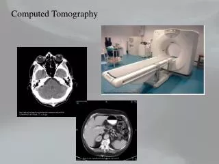
Chest X-Ray This frontal chest radiograph demonstrates a dense (radio-opaque)left lung field consistent with a hemothorax in a patient with agunshot wound to the chest. COMPUTED TOMPGRAPHY, CT This CT image demonstrates the large bullae characteristic of patients with Chronic Obstructive Pulmonary Disease (COPD) representing lung destruction
(From Siemens) (From Picker) Third & Fourth Generations
E-Beam CT Scanner • Speed: 50, 100 ms • Thickness: 1.5, 3, 6, 10 mm • ECG trigger cardiac images (From Imatron)
Spiral/Helical/Volumetric CT • Continuous & • Simultaneous • Source rotation • Patient translation • Data acquisition
Dual-slice Single-slice Quad-slice 1992 1989 1998 A rapid development
I0 I Projection Imaging with X Rays X-Ray Source Patient Detector
Image Analysis • Visualization & analysis • 3D, 4D • Networked, PC-based • Image fusion • Computer aided diagnosis • Image-based surgery
FUTURE • MONOENERGETIC RADIATION • DUAL ENERGY AROUND THE K-EDGE • ENERGY SENSITIVE PIXELDETECTORS
Projection & Sinogram Sinogram:All projections Projection:All ray-sums in a direction y P(t) t p x f(x,y) t X-rays Sinogram
Computed Tomography y Computed tomography (CT):Image reconstruction fromprojections t P(t) f(x,y) P(t) x f(x,y) X-rays
Reconstruction Idea =4 2=3 3=2 4=1
6 4 Error 0 0 4 3 3 2 Guess 1 0 0 2 1 3 2 Guess 0 2 4 3 Update a guessbased ondata differences Guess 2 -2 Error 2 1 Algebraic Reconstruction Technique(ART)
Fourier Transformation f(x,y) F(u,v) Fourier Transform Image Space Fourier Space
y P(t) t F[P(t)] x f(x,y) X-rays Fourier Slice Theorem v u F(u,v)
y v F-1[F(u,v)] x u f(x,y) F(u,v) P(t) From Projections to Image
P(t) P’(t) f(x,y) f(x,y) 1) Convolve projections with a filter 2) Backproject filtered projections Filtered Backprojection
Example: Projection Projection Projection Sinogram Ideal Image
Example: Backprojection Projection
Example: Backprojection Sinogram Backprojected Image
Example: Filtering Sinogram Filtered Sinogram
Example: Filtered Backprojection Filtered Sinogram Reconstructed Image