Download

1 / 30
300 likes | 324 Views
This workshop presentation discusses the use of permanent magnet helicon sources for various applications such as etching, coating, and propulsion. The presentation includes details on the design, optimization, and operation of these sources, along with experimental results and future plans.

E N D
Permanent-magnet helicon sources for etching, coating, and thrust Francis F. Chen, UCLA 2013 Workshop on Radiofrequency Discharges, La Badine, La Presqu’ile de Giens, France, 29-31 May 2013
Helicons are RF plasmas in a magnetic field Density increase over ICP UCLA
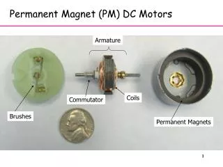
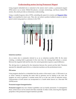
Helicon sources usually use heavy magnets The MØRI source of Plasma Materials Technologies, Inc. UCLA
The source has been simplified to this This uses a commercially available 2 x 4 x 0.5 inch NeFeB magnet The discharge is 5 cm high and 5 cm in diameter UCLA
Instead, we can use annular PMs PM Permanent magnet NdFeB ring magnet 3” ID, 5” OD, 1” high Stagnation point The far-field is fairly uniform Put plasma here or here, to adjust B-field UCLA
Optimized discharge tube: 5 x 5 cm 1. Diameter: 2 inches 2. Height: 2 inches 3. Aluminum top 4. Material: quartz 5. “Skirt” to prevent eddy currents canceling the antenna current The antenna is a simple loop, 3 turns for 13 MHz, 1 turn for 27 MHz. The antenna must be as close to the exit aperture as possible. Antenna: 1/8” diam tube, water-cooled UCLA
Experimental chamber The magnet height is set for optimum B-field Langmuir probes at three ports UCLA
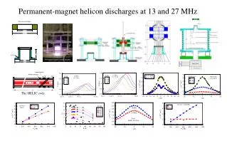
Optimization of the B-field Peak density in Port 2 vs. B and Prf @ 27 MHz 30-60 G is best UCLA
The HELIC code for helicon design D. Arnush, Phys. Plasmas 7, 3042 (2000). UCLA
Axial density profile inside the tube Density inside the tube is low (<1013 cm-3) because plasma is efficiently ejected. UCLA
Downstream density: 6 x 1011 cm-3 Density increase over ICP UCLA
Port 2 density is higher at 13 MHz This was a surprise and is contrary to theory. UCLA
Cause and location of the “double layer” F.F. Chen, Phys. Plasmas 13, 034502 (2006) Maxwellian electrons Bohm sheath criterion A sheath must form here Single layer forms where r has increased 28%
Probe ports An array source for roll-to-roll processing Height can be adjusted electrically if desired Aluminum sheet Z1 Z2 The source requires only 6” of vertical space above the process chamber. Two of 8 tubes are shown. UCLA
Top view of Medusa 2 Substrate motion Possible positions shown for 8 tubes.
Two arrangements of the array Staggered array Covers large area uniformly for substrates moving in the y-direction Compact array Gives higher density, but uniformity suffers from end effects.
Operation with cables and wooden magnet tray It’s best to have at least 3200W (400W per tube) to get all tubes lit equally.
Details of distributor and discharge tube The top gas feed did not improve operation. UCLA
A rectangular 50 transmission line 50-W line with ¼” diam Cu pipe for cooled center conductor
Density profiles with staggered array Staggered configuration, 2kW Bottom probe array Argon
Density profiles with compact array Compact configuration, 3kW Bottom probe array Data by Humberto Torreblanca, Ph.D. thesis, UCLA, 2008. UCLA
Plans for an 8-tube array for round substrates UCLA No center tube is necessary!
FIN Thank you