Download
1 / 28
280 likes | 497 Views
Modelling. Class T16: Conceptual Modelling – Architecture. Image from http://viz.cwrl.utexas.edu/taxonomy/term/52. Program. T01-T02 – Module 1 - Introduction to Systems Modeling T03-T06 – Module 2 - Conceptual Modeling – Domain T07-T11 – Module 3 - Conceptual Modeling – Behavior

E N D
Modelling Class T16: Conceptual Modelling – Architecture Image from http://viz.cwrl.utexas.edu/taxonomy/term/52
Program T01-T02 – Module 1 - Introduction to Systems Modeling T03-T06 – Module 2 - Conceptual Modeling – Domain T07-T11 – Module 3 - Conceptual Modeling – Behavior T12-T15 – Module 4 - Ontology T16 – Module 5 – Conceptual Modeling – Architecture (UML) T17 – … support for the project… T18 – Module 5 – Conceptual Modeling – Architecture (UML; SysML) T19 – …overview… T20-T21 – Module 6 - Conceptual Modeling – Methodologies T22-T23 – Module 7 - Ontology: Advanced T24-T25 - Conceptual Modeling – Global Revisions; Exercises, … Modelação
UML-Package Diagrams Modelação
Packages… A generic mechanism to group modeling elements Modelação
Packages… Modelação
Packages… Modelação
UML-Components Diagrams Modelação
Components Diagram (UML) • A Component Diagram illustrates the pieces of software, embedded controllers and such that make up a system, and their organization and dependencies. • A Component Diagram has a higher level of abstraction than a Class diagram; usually a component is implemented by one or more Classes (or Objects) at runtime. They are building blocks, built up so that eventually a component can encompass a large portion of a system. Modelação
Components Diagram (UML) • The dependencies among software systems’ components can be expressed in components diagrams: • Source code • Binary code • Executable code • Business processes… • Documents… • … • Example: UBL - Universal Business Language 2.0 • Schema Dependencies (http://docs.oasis-open.org/ubl/prd-UBL-2.0/) Modelação
Interfaces in Components • “Interfaces” are important to support replacement and re-usage... • A component initially designed for one specific system can be reused in another system… • A component can be replaced by other component… • … Modelação
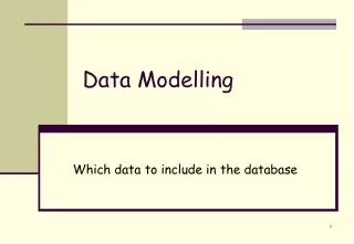
Components Diagram (UML) • Assembly connectors link the provided interfaces supplied by Product and Customer to the required interfaces specified by Order. • A Dependency relationship maps a customer's associated account details to the required interface Payment, indicated by Order. Modelação
Components can contain other components… wordsmith.dll Speller.obj Thesaurus.obj Speller.obj wordsmith.dll Thesaurus.obj Modelação
Elements in a Components Diagram Modelação
UML-Deployment Diagrams Modelação
Deployment Diagram • A Deployment diagram shows how and where the system is to be deployed; that is, its execution architecture. • Hardware devices, processors and software execution environments (system Artifacts) are reflected as Nodes, and the internal construction can be depicted by embedding or nesting Nodes. • As Artifacts are allocated to Nodes to model the system's deployment, the allocation is guided by the use of deployment specifications. Modelação Retirado do “Help” do Enterprise Architect
Deployment Diagram (example) • A hardware node • A software application • A specification (document) • A software component Modelação Retirado do “Help” do Enterprise Architect
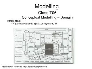
Deployment Diagram (Example) • Two Nodes have a TCP/IP communication path indicated. • Deployment relationships indicate the deployment of Artifacts. Furthermore, a deployment spec defines the process of deployment for the networkScanner Artifact. • The Manifestation relationships reveal the physical implementation of components ReposCustomer and ReposInternalRecords. Modelação Retirado do “Help” do Enterprise Architect
Deployment Diagram (Example) Nodes with components… Modelação
Nodes A node is a physical resource (computational node, a person, …) Modelação
Nodes and Instances of Nodes Modelação
Nodes and Components • Both can be part of generalizations, dependencies or associations… • Both can have instances… • But • Components are things that take part in the execution of a system • While • Nodes are things that execute components • Components represent groups of logical elements • While • Nodes represent the physical deployment of components Modelação
Nodes and Components (example) Modelação
Nodes and Components (example) Modelação
Nodes and Components (example) Cardinality… Modelação
Instances of Nodes and Components (example) “connection”: physical connections between nodes… Modelação
Modelação Image from http://blog.miragestudio7.com/wp-content/uploads2/2007/07/speedbump_comic_when_architects_propose_model_funny.gif