Download
1 / 26
260 likes | 376 Views
Computer Organization and Design Transistors & Logic - II. Montek Singh Wed, Oct 17, 2012 Lecture 11. Today ’ s Topics. Implementing digital logic transistor-level circuits gate-level circuits. From Transistors… to Gates!. We ’ ll use p-type here. and, n-type here. Logic Gate recipe:

E N D
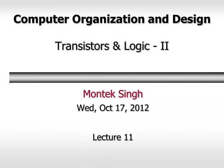
Computer Organization and DesignTransistors & Logic - II Montek Singh Wed, Oct 17, 2012 Lecture 11
Today’s Topics • Implementing digital logic • transistor-level circuits • gate-level circuits
From Transistors… to Gates! We’ll usep-type here and, n-typehere • Logic Gate recipe: • use complementary arrangements of PFETs and NFETs • called CMOS (“complementary metal-oxide semiconductor”) • at any time: either “pullup” active, or “pulldown”, never both! VDD pullup: make this connectionwhen VIN is near 0 so that VOUT = VDD VIN VOUT pulldown: make this connectionwhen VIN is near VDD so that VOUT = 0 Gnd
CMOS Inverter Valid “1” Invalid Valid “0” “1” “0” Only a narrow range of input voltages result in “invalid” output values. (This diagram is greatly exaggerated) “0” “1” A Y inverter Vout Vin Vout Vin
CMOS Complements A A B B conducts when A is highand B is high: A.B conducts when A is lowor B is low: A+B = A.B conducts when A is highor B is high: A+B conducts when A is lowand B is low: A.B = A+B A A B B A A conducts when A is high conducts when A is low Series N connections: Parallel P connections: Parallel N connections: Series P connections:
A Two Input Logic Gate A B What function does this gate compute? A B C 0 0 0 1 1 0 1 1
Here’s Another… B A What function does this gate compute? A B C 0 0 0 1 1 0 1 1
CMOS Gates Like to Invert B A Observation: CMOS gates tend to be inverting! • One or more “0” inputs are necessary to generate a “1” output • One or more “1” inputs are necessary to generate a “0” output • Why?
General CMOS Gate Recipe A B C B A C B A C A B C Step 1. Figure out pulldown network that does what you want (i.e the set of conditions where the output is ‘0’)e.g., F = A*(B+C) Step 2. Walk the hierarchy replacing nfets with pfets, series subnets with parallel subnets, and parallel subnets with series subnets Step 3. Combine pfet pullup network from Step 2 with nfet pulldown network from Step 1 to form fully-complementary CMOS gate.
One Last Exercise Vdd A B C F A B C • Lets construct a gate to compute: • F = A+BC = NOT(OR(A,AND(B,C))) • Step 1: Draw the pull-down network • Step 2: The complementary pull-up network
One Last Exercise Vdd A B C F A B C • Lets construct a gate to compute: • F = A+BC = NOT(OR(A,AND(B,C))) • Step 1: Draw the pull-down network • Step 2: The complementary pull-up network • Step 3: Combine and Verify 1 1 1 0 0 0 0 0
Now We’re Ready to Design Stuff! A Truth Table Y B C If C is 1 thencopy B to Y,otherwise copyA to Y • We need to start somewhere • usually it’s the functional specification If you are like most engineers you’d rather see a table, or formula than parse a logic puzzle. The fact is, any combinational function can be expressed as a table. These “truth tables” are a concise description of the combinational system’s function. Conversely, any computation performed by a combinational system can expressed as a truth table.
A Slight Diversion SURGE • Are we sure we have all the gates we need? • How many two-input gates are there? • All of these have 2-inputs (no surprise) • … 2 inputs have 4 possible values • How many possible patterns for 4 outputs are there? ___ • Generalizing, for N inputs, there are 2(2^N) gates AND OR NAND NOR 24
There Are Only So Many Gates How many of these gates can actually be implemented using a single CMOS gate? • There are only 16 possible 2-input gates • … some we know already, others are just silly • Do we need all of these gates? • Nope. We describe them all using AND, OR, and NOT.
We Can Make Most Gates Out of Others XOR B>A A B Y A A y Y B B • How many different gates do we really need?
One Will Do! = = = = = = • NANDs and NORs are universal • one can make any circuit out of just NANDs, or just NORs! • Ah! But what if we want more than 2-inputs?
Gate Trees A 0 0 1 1 B 0 1 0 1 C 0 1 1 0 Suppose we have some 2-input XOR gates: tpd = 1 And we want an N-input XOR: output = 1 iff number of 1s in input is ODD (“ODD PARITY”) N tpd = O( ___ ) -- WORST CASE. Can we compute N-input XOR faster?
Gate Trees 22 21 log2N 2 log N N-input TREE has O( ______ ) levels... Signal propagation takes O( _______ ) gate delays. log N
Design Approach: Sum-of-Products Truth Table Three steps: • Write functional spec as a truth table • Write down a Boolean expression for every ‘1’ in the output • Wire up the gates! • This approach will always give us logic expressions in a particular form: • SUM-OF-PRODUCTS • SUM actually means OR • PRODUCT actually means AND
Straightforward Synthesis A B C A B C Y A B C A B C • We can implement SUM-OF-PRODUCTS… • …with just three levels of logic • INVERTERS/AND/OR
Notations • Symbols and Boolean operators:
DeMorgan’s Laws • Change ANDs into ORs and vice-versa
C Useful Gate Structures A C Y B A Y B C A Y B DeMorgan’s Laws AB=A+B AB=A+B C A Y B • NAND-NAND • NOR-NOR “Pushing Bubbles” C A Y B C A Y B
An Interesting 3-Input Gate: Multiplexer Truth Table A Y B C If C is 1 thencopy B to Y,otherwise copyA to Y B C Y A • Based on C, select the A or B input to be copied to the output Y. 2-input Multiplexer A 0 B 1 Gate symbol C “schematic” diagram
Multiplexer (MUX) Shortcuts A0 B0 A1 B1 Y0 0 1S A B C D S 0 1 2 3 0 1S Y Y1 I0 I1 I2 I3 A0-3 B0-3 S A2 B2 A3 B3 Y0-3 0 1S Y2 Y 0 1 0 1 0 1 0 1 0 1 0 1 0 1 0 1S 0 1S Y3 0 1S 0 1S S0 S1 S A 4-bit wide 2-input Mux A 4-input Mux(implemented as a tree)
Next • Arithmetic Circuits