Download
1 / 68
710 likes | 1.12k Views
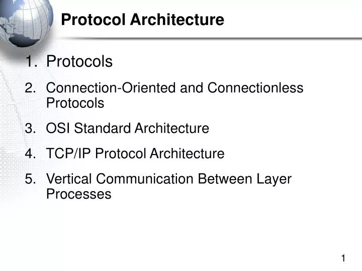
Protocol Architecture. Protocols Connection-Oriented and Connectionless Protocols OSI Standard Architecture TCP/IP Protocol Architecture Vertical Communication Between Layer Processes. 1. Protocols. Key Elements of a Protocol. Syntax Data formats Signal levels Semantics

E N D
Protocol Architecture • Protocols • Connection-Oriented and Connectionless Protocols • OSI Standard Architecture • TCP/IP Protocol Architecture • Vertical Communication Between Layer Processes
Key Elements of a Protocol • Syntax • Data formats • Signal levels • Semantics • Control information • Error handling • Timing • Speed matching • Sequencing
Standards Standards are rules of operation that allow two hardware or software processes to work together Even if they are from different vendors
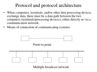
Figure 2-1: Standards Govern the Exchange of Messages • Standards Govern the Exchange of Messages • Messages must be governed by strict rules • Because computers are not intelligent Message
Figure 2-1: Standards Govern the Exchange of Messages (Continued) • Standards Govern Syntax • Syntax: the organization of the message • Human example: “Susan thanked Tom” • This sentence has a subject-verb-object syntax • Standards Govern Semantics • Semantics: The meaning of the message • Human example: “Susan thanked Tom” • Humans understand this message easily
Figure 2-1: Standards Govern the Exchange of Messages, Continued • General Message Syntax (Organization) • General Message Organization (Figure 2-4) • Primary parts of messages • Data Field (content to be delivered) • Header (everything before the data field) • Trailer (everything after the data field) • The header and trailer act like a delivery envelope for the data field. Trailer Data Field Header
Figure 2-1: Standards Govern the Exchange of Messages, Continued • General Message Syntax (Organization) • Header and trailer are further divided into fields Trailer Data Field Header Other Header Field Destination Address Field is Used by Switches and Routers Like the Address on an Envelope Message with all three parts
Figure 2-4: General Message Organization, Continued Data Field Header Other Header Field Destination Address Field Message without a trailer Usually only data link layer messages have trailers
Figure 2-4: General Message Organization, Continued Header Message with only a header e.g. TCP supervisory messages are pure headers (there is no data field content to deliver) Other Header Field Destination Address Field
A B Open Connection Message 2 (Seq. Num = A2) Message 3 (Seq. Num B1) Figure 2-6: Connection-Oriented and Connectionless Protocols Connection-Oriented Protocol Connectionless Protocol A B Message (No Sequence Number) Message 1 (Seq. Num = A1) Connection-oriented protocols Formal openings and closings Also have sequence numbers so that the receiver can put messages in order And so the receiver can send Acknowledgments for specific messages Close Connection
Figure 2-6: Connection-Oriented and Connectionless Protocols, Continued Client PC Browser Webserver Application HTTP Request HTTP is connectionless No Openings No Closings No Sequence Numbers No Acknowledgments
Figure 2-6: Connection-Oriented and Connectionless Protocols, Continued In TCP Client PC TCP Process Webserver TCP Process Connection-Opening Messages Messages During the Connection Time Connection-Closing Messages
Figure 2-7: Advantages and Disadvantages or Connection-Oriented Protocols • Advantages • Thanks to sequence numbers, the parties can tell if a message is lost. • Error messages, such as ACKs can refer to specific messages. • Long messages can be fragmented into many smaller messages that can fit inside packets. • Fragmentation followed by reassembly on the destination host is an important concept in networking.
Figure 2-7: Advantages and Disadvantages or Connection-Oriented Protocols, Cont. • Disadvantages • The presence of many supervisory messages consumes existing bandwidth • The processing of connection information places a heavy processing load on computers connected to the network
Standards Architecture • A Standards Architecture is a Broad Plan for Creating Standards • Break the problem of effective communication into smaller pieces for ease of development • Develop standards for the individual pieces • Just as a building architect creating a general plan for a house before designing the individual rooms in detail
OSI • Open Systems Interconnection • Developed by the International Organization for Standardization (ISO) • Seven layers • A theoretical system delivered too late! • TCP/IP is the de facto standard
OSI - The Model • A layer model • Each layer performs a subset of the required communication functions • Each layer relies on the next lower layer to perform more primitive functions • Each layer provides services to the next higher layer • Changes in one layer should not require changes in other layers
Why Layer? • Breaking up large tasks into smaller tasks and assigning tasks to different individuals is common in all fields • Specialization in standards design (EEs for physical layer, application specialists for application layer, etc.) • Simplification in standards design for individual standards • If you change a standard at one layer, you do not have to change standards at other layers
Protocol Data Units (PDU) • At each layer, protocols are used to communicate • Control information is added to user data at each layer (PDU = Control + Data) • Transport layer may fragment user data • Each fragment has a transport header added • Destination SAP • Sequence number • Error detection code • This gives a transport protocol data unit
TCP/IP Protocol Architecture • Developed by the US Defense Advanced Research Project Agency (DARPA) for its packet switched network (ARPANET) • Used by the global Internet • No official model but a working one. Application layer Transport layer Internet layer Data Link layer (Network Access) Physical layer (host-to-host)
Figure 2-8: Hybrid TCP/IP-OSI Architecture, Continued • Physical and Data Link Layer Standards • Govern Communication Through a Single Network • LAN or WAN
Physical Layer • Physical interface between data transmission device (e.g. computer) and transmission medium or network • Characteristics of transmission medium • Signal levels • Data rates • etc.
Figure 2-9: Physical and Data Link Layer Standards in a Single Network • Physical Layer • Physical layer standards govern transmission between adjacent devices connected by a transmission medium Physical Link A-X1 Switch X1 Host A Switch X2 Physical Link X1-X2
Figure 2-9: Physical and Data Link Layer Standards in a Single Network, Continued • Data Link Layer • Data link layer standards govern the transmission of frames across a single network—typically by sending them through several switches along the data link Data Link A-B Host B Switch X1 Host A Switch X2
Figure 2-9: Physical and Data Link Layer Standards in a Single Network, Continued • Data Link Layer • Data link layer standards also govern • Frame organization • Switch operation
Figure 2-9: Physical and Data Link Layer Standards in a Single Network, Continued 3 Physical Links 1 Data Link 2 Switches Host A Switch Data Link A-R1 Switch Physical Link A-X1 Server Station Switch X1 Physical Link X1-X2 Physical Link X2-R1 Switch X2 Mobile Client Station Router R1
Figure 2-10: Internet and Data Link Layers in an Internet • Internet and Transport Layers • An internet is a group of networks connected by routers so that any application on any host on any network can communicate with any application on any other host on any other network • Internet and transport layer standards govern communication across an internet composed of two or more single networks
Figure 2-10: Internet and Data Link Layers in an Internet, Continued • Internet Layer • Internet layer standards govern the transmission of packets across an internet—typically by sending them through several routers along the route • Messages at the internet layer are called packets • Internet layer standards also govern packet organization and router operation Router 1 Router 2
Figure 2-10: Internet and Data Link Layers in an Internet, Continued Host A Data Link A-R1 R1 Network X Network Y 3 Data Links: One per Network 1 Route per Internet Data Link R1-R2 Route A-B Network Z R2 Host B Data Link R3-B
Figure 2-10: Internet and Data Link Layers in an Internet, Continued Frame X Packet Data Link A-R1 Switch In Network X: Two Destination Addresses: Packet: Host B (Destination Host) Frame: Router R1 Host A Switch Server Station Switch X1 Mobile Client Station Switch X2 Route A-B Router R1 Network X
Figure 2-10: Internet and Data Link Layers in an Internet, Continued To Network X Route A-B Router R1 Frame Y Data Link R1-R2 In Network Y: Two Destination Addresses: Packet: Host B (Destination Host) Frame: Router R2 Packet Router R2 Network Y To Network Z
Figure 2-10: Internet and Data Link Layers in an Internet, Continued Frame Z Packet Data Link R2-B Switch Z1 Host B Router R2 In Network Z: Two Destination Addresses: Packet: Host B (Destination Host) Frame: Host B Switch Z2 Mobile Client Stations Switch X2 Router Network Z
Frames and Packets • In an internet with hosts separated by N networks, there will be: • 2 hosts • One packet (going all the way between hosts) • One route (between the two hosts) • N frames (one in each network) • N-1 routers (change frames between each pair of networks) • There usually are many switches within single networks • There usually are many physical links within networks
Figure 2-11: Internet and Transport Layer Standards • Transport Layer • Transport layer standards govern aspects of end-to-end communication between two end hosts that are not handled by the internet layer • These standards allow hosts to work together even if the two computers are from different vendors and have different internal designs
Figure 2-11: Internet and Transport Layer Standards, Continued Transport Layer end-to-end (host-to-host) TCP is connection-oriented, reliable UDP is connectionless and unreliable Server Client PC Internet Layer (usually IP) hop-by-hop (host-router or router-router) connectionless, unreliable Router 1 Router 2 Router 3
Figure 2-12: Application Layer Standards • Application Layer • The application layer governs how two applications work with each other, even if they are from different vendors Browser Webserver Application Webserver Client PC
Figure 2-12: Application Layer Standards • There are more application layer standards than any other type of standard because there are many applications • HTTP • E-Mail • Database • Instant Messaging • FTP • Etc.
Figure 2-18: Layered Communication on the Source Host The process begins when a browser creates an HTTP request message Application Process HTTP Message Passes Message Down to Transport Process Transport Process HTTP Message TCP Hdr Encapsulation of HTTP Message in Data Field of TCP Segment