Download
1 / 13
130 likes | 290 Views
LCLS-II Power Coupler. Nikolay Solyak , Ivan Gonin , Andrei Lunin C.Adolphsen - SLAC TTC meeting, March 23-27, 2014. Preliminary. LCLS-II Coupler Technical Specs. Fundamental Power Coupler (FPC). XFEL (modified TTF3) coupler is not meet LCLS-II requirements

E N D
LCLS-II Power Coupler Nikolay Solyak, Ivan Gonin, Andrei Lunin C.Adolphsen- SLAC TTC meeting, March 23-27, 2014 AWLC2014, FNAL, May 12-16, 2014
Preliminary • LCLS-II Coupler Technical Specs AWLC2014, FNAL, May 12-16, 2014
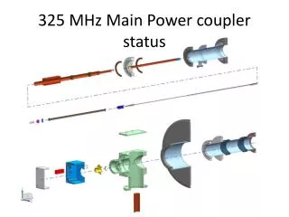
Fundamental Power Coupler (FPC) • XFEL (modified TTF3) coupler is not meet LCLS-II requirements • Tuning range (1.e6-1.e7) not cover required Qext=4.e7 • Overheating of the internal bellow in warm section at 7kW CW power at full reflection (effective power ~14kW) • Two modifications were proposed to address these problems (R&D program: Four coupler modification test) • Cut antenna 8.5mm to increase Qext • Increase copper plating of internal inner conductor of warm section from 30 μm to 100-150 μm to eliminate overheating TTF-3 design AWLC2014, FNAL, May 12-16, 2014
Inner conductor: Temperature distribution for different thickness of copper coating and different RRR (15kW, TW-regime) Tmaxlimit Data is simulated for RRR=10 Copper plating at inner part is 100 microns Conclusion: TTF3 Coupler need to be modified for LCLS-II. 100-150 μm Cu plating inner conductor in warm section of coupler is possible solution. AWLC2014, FNAL, May 12-16, 2014
LCLS-II Cavity Qext Computation LCLS-II specs Q ext– range for ±7.5mm antenna tuning Nominal positions Original XFEL antenna Antenna tip cut by 8.5 mm Qext ~ 4.0·106 Qext ~ 2.4·107 R3 R3 AWLC2014, FNAL, May 12-16, 2014 A. Lunin, 12/13/13
Qext sensitivity to antenna displacements (ILC vs. LCLS-II) Horizontal LCLS-II Horizontal XFEL Vertical XFEL Vert. antenna tilt (up and down) Horiz. antenna tilt along cavity axis A.Lunin • Conclusion • For LCLS-II coupler the most sensitive parameter is a horizontal antenna shift/tilt. • ± 5 mm shift change Qext by -5%/+50%. Vertical tolerances are relaxed. AWLC2014, FNAL, May 12-16, 2014
TTF-3 Coupler: Inner coating 30µm, outer coating 10µm. Helium cooling of the warm section 7kW TW TTF3 original coupler 7kW TW I.Gonin (FNAL) Helium, P=1atm Window force 160N Power Losses and max. Temp Ivan Gonin, FNAL AWLC2014, FNAL, May 12-16, 2014
Full reflection: E-field distribution in LCLS-II coupler, Q=4e7, Pin=7kW AWLC2014, FNAL, May 12-16, 2014
Coupler operation at 7kW CW at full reflection PEC BC L=0 LCLS-II Coupler. Inner coating 100µm. Outer coating 10µm L Off resonance On resonance Temperature distribution along surface of inner conductor for TW and SW ( L=0mm & L=65mm ) Maximum Temperature vs. L On resonance Tmax ~425K AWLC2014, FNAL, May 12-16, 2014
Coupler test in HTS -1 Operational for ~5 yrs (~2 cavity/month throughput) • 1.3 GHz and 3.9 GHz cavities, ~1.5 ms and 9ms RF pulses • Now HTS upgraded for CW operation (commissioning) • Priorities in FY14 (CW regime) • HOM feedthu’s(XFEL and JLAB designs) • 3 tests of high-Q0 dressed cavity (1 dressed to ILC helium vessel and 2 dressed to LCLS-II vessel) • 2 modified at SLAC Power Couplers • Integrated test of dressed cavity with Slow/Fast tuners, Frequency control and μ-phonics AWLC2014, FNAL, May 12-16, 2014
Active Magnetic shielding 500 mGs - 500 mGs Inside 1-layer magnetic shielding after active correction by coils Max magnitude < 6mG Inside 1-layer magnetic shielding Max magnitude < 45mGs AWLC2014, FNAL, May 12-16, 2014
HTS test preliminary schedule • Assumptions about readiness: • 2 modified “cold” parts of FPC: April (done) • 2 modified “warm” parts of FPC: June • 4 LCLS-II type of Helium Vessels: end of July • JLAB feedthru: end of June • New lever tuner and 2-layer shielding: Sept. AWLC2014, FNAL, May 12-16, 2014
Conclusion • XFEL coupler not meet LCLS-II specifications. Problems: Qext range and overheating • 2 major modification was proposed: shorter antenna (by 8.5mm) and thicker (>100μm) Cu plating of inner conductor in warm section to address these problems: • Modifications are in progress at SLAC (cold part modification was done, warm sections of couplers will be ready by the end of June 2014, plated at CPI and processed at SLAC). • HTS tests is essential part of design verification program for LCLS-II. • 3 high Q0 (N2 doped) integrated tests , (HOM feedtru’s, FPC, Helium vessel, Tuner, magnetic shielding) • two modified FPC assembled on high-Qo cavity. • Next step: start FPC procurement after HTS tests. • Documentations and review. AWLC2014, FNAL, May 12-16, 2014