Download
1 / 20
260 likes | 419 Views
Explore the principles of magnetic force on conductors in electric motors. Discover how current, field, and angle affect force, and learn about parts and operation of electric motors.

E N D
Electric Motor www.assignmentpoint.com
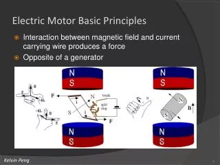
Magnetic Force On A Current – Carrying Conductor • The magnetic force (F) the conductor experiences is equal to the product of its length (L) within the field, the current I in the conductor, the external magnetic field B and the sine of the angle between the conductor and the magnetic field. In short F= BIL (sin) www.assignmentpoint.com
The force on a current-carrying conductor in a magnetic field: • When a current-carrying conductor is placed in a magnetic field, there is an interaction between the magnetic field produced by the current and the permanent field, which leads to a force being experienced by the conductor: www.assignmentpoint.com
The magnitude of the force on the conductor depends on the magnitude of the current which it carries. The force is a maximum when the current flows perpendicular to the field (as shown in diagram A on the left below), and it is zero when it flows parallel to the field (as in diagram B, on the right): www.assignmentpoint.com
Fleming’s left-hand rule www.assignmentpoint.com
The directional relationship of I in the conductor, the external magnetic field and the force the conductor experiences I B F www.assignmentpoint.com
Motion of a current-carrying loop in a magnetic field Rotation F I R N L S F brushes Commutator (rotates with coil) www.assignmentpoint.com
Vertical position of the loop: Rotation N S www.assignmentpoint.com
Electric Motor • An electromagnet is the basis of an electric motor • An electric motor is all about magnets and magnetism: A motor uses magnets to create motion. • Opposites attract and likes repel. Inside an electric motor, these attracting and repelling forces create rotational motion. • A motor is consist of two magnets. www.assignmentpoint.com
Parts of the Motor • Armature or rotor • Commutator • Brushes • Axle • Field magnet • DC power supply of some sort www.assignmentpoint.com
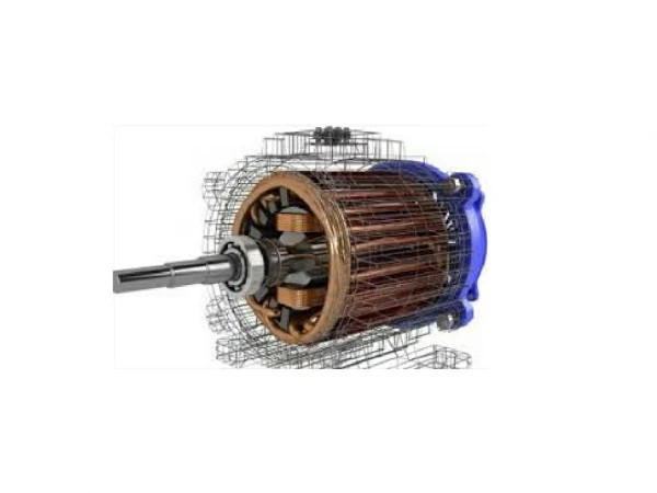
Motor Illustration www.assignmentpoint.com
Armature • The armature is an electromagnet made by coiling thin wire around two or more poles of a metal core. • The armature has an axle, and the commutator is attached to the axle. • When you run electricity into this electromagnet, it creates a magnetic field in the armature that attracts and repels the magnets in the stator. So the armature spins through 180 degrees. • To keep it spinning, you have to change the poles of the electromagnet. www.assignmentpoint.com
Commutator and Brushes • Commutator is simply a pair of plates attached to the axle. These plates provide the two connections for the coil of the electromagnet. • Commutator and brushes work together to let current flow to the electromagnet, and also to flip the direction that the electrons are flowing at just the right moment. www.assignmentpoint.com
The contacts of the commutator are attached to the axle of the electromagnet, so they spin with the magnet. The brushes are just two pieces of springy metal or carbon that make contact with the contacts of the commutator. www.assignmentpoint.com
Spinning Armature www.assignmentpoint.com
Example of Motor www.assignmentpoint.com
Answer the questions www.assignmentpoint.com
A current-carrying coil in a magnetic field experiences a turning effect. How can the turning effect be increased? A increase the number of turns on the coil B reduce the size of the current C reverse the direction of the magnetic field D use thinner wire for the coil www.assignmentpoint.com
What are the directions of the force in the left and right loop? www.assignmentpoint.com
A student sets up the apparatus shown in order to make a relay. Which metal should be used to make the core? A aluminium B copper C iron D steel www.assignmentpoint.com