Download
1 / 90
1.13k likes | 1.96k Views
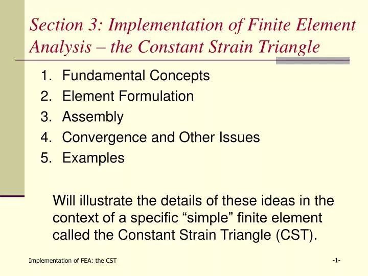
Section 3: Implementation of Finite Element Analysis – the Constant Strain Triangle. Fundamental Concepts Element Formulation Assembly Convergence and Other Issues Examples.

E N D
Section 3: Implementation of Finite Element Analysis – the Constant Strain Triangle • Fundamental Concepts • Element Formulation • Assembly • Convergence and Other Issues • Examples Will illustrate the details of these ideas in the context of a specific “simple” finite element called the Constant Strain Triangle (CST).
Section 3: Implementation of FEA – the CST Overview: What is Finite Element Analysis? • Assume a given problem is to be solved globally over some object. FEA proceeds as follows: • Discretize the problem into a finite number of “local” approximate problems on regions called elements. • Set up and solve each of the local approximate problems. • Assemble the local solutions into a global solution. • Check convergence. (If not converged, repeat steps #2 and #3.) • Once converged, evaluate the solution. Your responsibility! (Program does the rest.)
Section 3.1: Fundamental Concepts • An element is a small piece of an overall object characterized by: • Its type(truss, beam, plate, solid, …) • Its geometry(1D, 2D, or 3D; line, triangle, rectangle, tetrahedron, “brick”, …) • Its nodes(corner, interior, …) anddegrees of freedom(displacement, rotation, …) • Its shape functions What is an element?
3.1: Fundamental Concepts (cont.) Nodes and Degrees of Freedom – • Elements are restricted in how they can behave. • E.g., beam element from HW #1: • No left/right motion allowed; only certain types of bending possible. • It is required that the complete range of possible behaviors be determined by the locations of the nodes, the basic behaviors allowed at each node (degrees of freedom), and the shape functions used.
3.1: Fundamental Concepts (cont.) Required Properties of the Approximate Solution: • Well-posedness: the number of shape functions used in the approximate solution must equal the number of degrees of freedom. • Degrees of freedom are the unknowns in the local problem; need one equation per unknown to get unique solution. • E.g., Galerkin’s method:
3.1: Fundamental Concepts (cont.) Required Properties of the Approximate Solution: • Differentiability: The shape functions must be continuous and have continuous derivatives up to an order consistent with the variational principle used. • Defines behavior within element. • In general, if nth order derivative is in variational principle, then shape functions must have continuous derivatives of order n-1. • Prevents integrals from “blowing up” or becoming undefined.
3.1: Fundamental Concepts (cont.) • Example: 1D Axial Rod “dynamics” • Variational principle before integrating by parts was Requires continuous 1st derivatives for u(x). • Variational principle after integrating by parts was Requires continuous u(x).
3.1: Fundamental Concepts (cont.) Required Properties of the Approximate Solution: • Completeness: approximate solution must be able to represent two special displacement states exactly – • Rigid body motion: all points in element have same values of displacement. • Constant strain state: all normal strains and shearing strains have a fixed value everywhere in the element.
3.1: Fundamental Concepts (cont.) Required Properties of the Approximate Solution: • Rigid body motions cannot create strain energy, so no strains present anywhere constant displacement.
3.1: Fundamental Concepts (cont.) Required Properties of the Approximate Solution: • As element size becomes very small, expect internal strains to change very little at different points in element. If approximate solution cannot support this, expect problems in convergence.
3.1: Fundamental Concepts (cont.) Required Properties of the Approximate Solution: • Compatibility: If two elements share a boundary, the shape functions must permit an appropriate level of continuity across the boundary. • Prevents “gaps” or “kinks” from developing in global solution. • Elements with this property are called conforming. • For more complicated elements, compatibility may be required only at selected points on the boundary. (Such elements are called non-conforming.)
3.1: Fundamental Concepts (cont.) • Example: Two constant strain triangles • For element #1, displacements at P depend on coordinates of point and the values (u1, v1, u2, v2, u3, v3). • For element #2, displacements at P depend on coordinates of point and the values (u1, v1, u2, v2, u4, v4).
3.1: Fundamental Concepts (cont.) • Displacement continuity then requires at all pointsP and for all values of (u1, v1, u2, v2, u3, v3, u4, v4). • Can show that this requirement will be satisfied if (Displacements on a boundary depend only upon the nodes on that boundary!)
Section 3.2: Element Formulation The Constant Strain Triangle element: • 2D element used in plane stress and plane strain problems • Nominal thickness = h(small; can be variable) • Three corner nodes withcoordinates (xi, yi) • Two degrees of freedom per node: (ui, vi)
3.2: Element Formulation (cont.) Two approaches for generating shape functions: • “Interpolation approach”: • Matrix-based method • Works best for small numbers of d.o.f. • “Direct approach”: • More geometric method • Works best for higher-order elements (Other methods also exist; will not discuss these much.)
3.2: Element Formulation (cont.) Some basic ideas (for both approaches): • 6 d.o.f. total 6 shape functions. • Fundamental unknowns are horizontal displacement u(x,y) and vertical displacement v(x,y). • Each displacement expected to use 3 shape functions. • Rule of thumb: simple shape functions = better shape functions.(easier to integrate, more widely applicable, …) • For 2D elements, polynomials in x and y are most common choice for shape functions. • If you have derivatives of order n in your variational principle, it is best to choose your shape functions so that they can form a complete polynomial of order n. (Gives control over errors, faster convergence, …)
3.2: Element Formulation (cont.) Pascal’s triangle (Row n+1 based upon expansion of (x+y)n. )
3.2: Element Formulation (cont.) “Interpolation approach”: • Approximate u(x,y) and v(x,y) by complete 1st order polynomials: • At each node, require u(xi,yi) = ui and v(xi,yi) = vi: 6 equations for the 6 unknowns!
3.2: Element Formulation (cont.) “Interpolation approach”: • Write this in matrix form: • Solution (in symbolic form) is
3.2: Element Formulation (cont.) “Interpolation approach”: • Now, rewrite interpolation functions in matrix/vector form: • Substitute previous result: Matrix of shape functions!
3.2: Element Formulation (cont.) “Interpolation approach”: • For CST, can show that
3.2: Element Formulation (cont.) Notes on “Interpolation approach”: • This approach generalizes to different shapes, different node locations, and different numbers of d.o.f. (See Prob. 3.1 and 3.2 in Schaum’s Outline.) • However, the matrix [C] is not always invertible for general choices of nodal locations. • As number of d.o.f. increases, matrix inversion becomes more difficult, and thus exact functions become harder to determine.
3.2: Element Formulation (cont.) “Direct approach”: Need two “facts” about shape functions – • u(x,y) and v(x,y) are complete 1st order polynomials: • Suppose I know the shape functions already: Shape functions must be linear in both x and y. Kronecker delta property
3.2: Element Formulation (cont.) • Visually, this looks like:
3.2: Element Formulation (cont.) • Consider the shape function corresponding to u1: • Therefore, get a set of equations to solve: • Similar procedure to construct other shape functions.
3.2: Element Formulation (cont.) Notes on “Direct approach”: • This approach is more commonly used as number of d.o.f. and/or order of polynomials used increases. • Works best if shape functions are computed on “standard” geometries – leads to so-called “isoparametric formulation”.
3.2: Element Formulation (cont.) Check the required properties: • Well-posedness: 6 d.o.f and 6 shape functions. • Differentiability: Will show that only 1st derivatives show up in variational principle, so need continuous shape functions. • Completeness – • Rigid body motion: Suppose
3.2: Element Formulation (cont.) Check the required properties: • Completeness – • Constant strain: Can • Continuity: In fact, strain must be a constant ! Neither N3(x,y) nor N4(x,y) can influence what happens on the line between pt. 1 and pt. 2. Only d.o.f. at pt. 1 and pt. 2 matter!
3.2: Element Formulation (cont.) Next issue: deriving the approximate equations • Determine element (local) stiffness matrix • Relates forces (stresses) to displacements (strains) • Term is used for all elements, not just elastic ones • Determine element (local) force vector • Includes both body forces and surface tractions • Will change during the course of solving a problem
3.2: Element Formulation (cont.) Goal: obtain approximate solution to 2D elasticity equations – Galerkin, Calculus of Variations, Rayleigh-Ritz, …
3.2: Element Formulation (cont.) Using Calculus of Variations (aka Principle of Virtual Displacements): • Key Idea: solve same problem locally –
3.2: Element Formulation (cont.) New Goal: obtain approximate solution to 2D elasticity equations on each element –
3.2: Element Formulation (cont.) Strain-Displacement Relations – • Relate u to εas follows: • Using shape functions: Derivative operator matrix,
3.2: Element Formulation (cont.) Stress-Strain Relations – • Relate σ to εas follows: • Using previous results: Not the same as used in interpolation approach!
3.2: Element Formulation (cont.) Element (Local) Stiffness Matrix – • Put these results into 1st term of PVD: Element stiffness matrix, [k].
3.2: Element Formulation (cont.) Notes on Element (Local) Stiffness Matrix – • The element stiffness matrix for any elastic element will follow the exact same process. (Details will change.) • Element stiffness matrix is symmetric.
3.2: Element Formulation (cont.) Notes on Element (Local) Stiffness Matrix – • [k] for the CST element is: (See Probs. 3.14, 3.19, and 3.40 in Schaum’s.)
3.2: Element Formulation (cont.) Element (Local) Force Vector – • Evaluate 2nd and 3rd terms of PVD: Element force vector (f)
3.2: Element Formulation (cont.) Notes on Element (Local) Force Vector – • In general, b and tcan depend upon position, so they are left inside of the integrals. • A “physical” interpretation of f: Called equivalent nodal force
3.2: Element Formulation (cont.) A “truss analogy” for elements –
3.2: Element Formulation (cont.) Example – • Given: CST element shown has no body force and a surface traction applied to edge 23 expressed as • Required: Find (f).
3.2: Element Formulation (cont.) Example – • Solution:
3.2: Element Formulation (cont.) Example – • Solution:
3.2: Element Formulation (cont.) Example – • Solution:
Section 3: Implementation of FEA – the CST Overview: What is Finite Element Analysis? • Assume a given problem is to be solved globally over some object. FEA proceeds as follows: • Discretize the problem into a finite number of “local” approximate problems on regions called elements. • Set up each of the local approximate problems. • Assemble the local problems into a global problem. • Solve the global problem and check convergence. (If not converged, repeat steps #2 and #3.) • Once converged, evaluate the solution.
Section 3.3: Assembly • Each degree of freedom diin a given element corresponds to a unique degree of freedom Dkin the overall object. • Each local stiffness matrix [k]e contributes to part of the global stiffness matrix of the object, [K]. • Also, each local force vector (f)e contributes to part of the global force vector of the object, (F). Concept of assembly: Global Local
3.3: Assembly (cont.) Concept of Assembly: • Assembly is not straight addition –
3.3: Assembly (cont.) How is assembly done in FEA programs? • Each element has an associated “map” that contains connectivity information; i.e., it links each local d.o.f. to corresponding global d.o.f. for the given element). • Various names: “Connectivity vector”, “destination array”, “element-node array”, … • For picture on Slide 2:
3.3: Assembly (cont.) Pseudocode for Assembly: For e = 1, numel ← sum over all elements For i = 1, numdof(e) ← sum over all local d.o.f. For j = i, numdof(e) ← local d.o.f. ii = map(e,i); jj = map(e,j); ← get global d.o.f. K(ii,jj) = K(ii,jj) + k(e,i,j); ← assemble [K] Continue F(ii) = F(ii) + f(e,i); ← assemble (F) Continue Continue