Download
1 / 37
370 likes | 380 Views
Learn about the design challenges faced in building the MEG experiment's liquid Xenon cryostat, meeting stringent technological requirements & testing procedures.

E N D
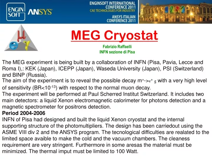
MEG Cryostat Fabrizio Raffaelli INFN sezione di Pisa The MEG experiment is being built by a collaboration of INFN (Pisa, Pavia, Lecce and Roma I),: KEK (Japan), ICEPP (Japan), Waseda University (Japan), PSI (Switzerland) and BINP (Russia). The aim of the experiment is to reveal the possible decay m+->e+g with a very high level of sensitivity (BR<10-13) with respect to the normal muon decay. The experiment will be performed at Paul Scherred Institut Switzerland. It includes two main detectors: a liquid Xenon electromagnetic calorimeter for photons detection and a magnetic spectrometer for positrons detection. Period 2004-2006 INFN of Pisa had designed and built the liquid Xenon cryostat and the internal supporting structure of the photomultipliers. The design has been carriedout using the ASME VIII div 2 and the ANSYS program. The tecnological difficulties are realated to the limited space avaible to make the cold and the vacuum chambers. The cleaness requirement are very stringent. Furthermore in some aresas the material must be minimized. The thermal imput must be limited to 100 Watt.
MEG Cryostat Experimental area at Paul Scherred Institut (PSI) Liquid Xenon cryostat
Materials and space limits Vacuum chamber Cold chamber Cryostat must be positioned with the internal detecting structure with a precision of a couple of mm respect the Superconducting magnet (Corba). The limited space between the magnet and the cryostat dose not allowed to make the flanges of the cold chamber enough stiff. The material used must have a magnetic relative permeability less of 1.008 to damage to the superconductive magnet. Usually the austenitic stainless steel have a relative permeability equal or bigger or than 1.01. For this reason many parts are made in 25 Cr-20Ni SA-240 Plate ASME 310S. CORBA Magnet
Limted material areas In the angular regions between +/-630 and longitudinal +/-250. the material thickness must be limited as much as possible.
CORBA Supercondacting magnet Warm magnet ouround the S.M. are used to to cancel the magnetic field i saome areas. Materials oround with magnetic permeability bigger than 1.008 can casue forces on the cold mass such to break the magnet Corba magnet: central part is made by a superconducive magnet with an alluminum cryostat such that will be as mauch as possible transparent to the particles.
Some tecnical requirements Cold Chamber: Working temperature 165K; design and test pressure respectively of 0.2 Mpa e 0.4 Mpa. Leak rate below 10-9 atm cm3/sec. This last requirements implied the use of metallic seals. Typical pre-setting values are 285 Newton/mm. Welding procedures must guarantee the cleanness of inner surfaces Xeno must not enter in front of the detecting system Vacuum chamber: External pressure 0.1 Mpa at the working temperature of 20 0C
The front part of the internal structure must be adherent to the cold windows Peek AISI 316L Aluminum 5083-0
Inner Vessel flanges Cold chamber the space avaible has force us to limited the flanges dimension and study the positiong of the welding.
Intermediate test during construction. Cold chamber: After the warm and cold chambers have been welded. We test them with helium. Sealing the volume using covers with special compound to verify that no leak are present in the weddings and materials. The Fea model in this configuration shown excessive deformation that does not allowed to make the test on the cold chamber. This test was possible only adding an internal structure to stiffening the chamber.
Intermediate test during construction Cold chamber: case open with cover not connected under an external pressure of 0.1 Mpa. In the first attemped to make vacuum. We stopped the test after the structure move of 20 mm loosing the thightness. The model shows the max deformation of 40mm and high stress on the inner ring.
Intermediate test during construction Vacuum chamber: no cover under an external pressure of 0.1 Mpa. In the lower part reinforced plate were welded in the corrispondence of the supports.
1 4 3 2 Pressure test of the cold vessel max displacement measured at the pressure test 4 bar Dial indicator 1 disp.= 1.2 mm Dial indicator 2 disp.= 1.25 mm Dial indicator 3 disp.= 0.55 mm Dial indicator 4 disp.= 0.055mm 1.3 mm Dial. N.1 1.7 mm Dial. N. 2
cover According to ASME the thickness of flanges are undersize considering the allowable stress. However we reinforced the weldings with a large fillet. front wall cover outer wall inner wall front wall head
After the qualification test we do the final machining to prepare it for the windows weldings. Welding foil of 0.3mm to garantee the sealing and cleneass.
Windows designs 0.3mm sheet to seal the liquid Xeno Honeycomb and carbon fiber panel Cold chamber 0.3 mm sheet window vacuum chamber
Welding of the parts. Three days for welding the foil and 3 days to check and repair leaks test box. • WARM WINDOW
H2O • 100 mm • 1E,1C • 2E,2C • 3E, 3C Vacuum window test We repet thress time the measuraments to verify the stability of the vaccum window. The menbranal stress in the central part is 250 Mpa. We were more anbicius thinking to use .15mm sheet, but we had weldings problems, finally the thickness used was 0.3mm Four steps: 0.6 bar, 0.9 bar, 1.2 bar, 1.5 bar
Test of the vaccum chamber Dialed indicator positions
A good agreement on the measurements 2mm were measured
2mm misurato Lateral plugs Small window 0.1mm SS. sheets Liquid Xeno Vacuum 21
2mm misurato Cold window first panel carbon fiber aluminum honeycomb High module pitch carbon fiber 550Gpa 6 plies (0/+45/-45)s Total Thickness .7mm per skins Honeycomb thickness 19 mm Density 50Kg/m3. Glued with film adhesive Redux 312UL. Material with low outgassing rate resin cyanate ester 22
2mm misurato First Panel The film adhesive used Redux 312UL (-55 0C) is not suitable for the nitrogen temperature (-200 0C) The pitch fibers used are very brittle. Delaminations around the holes are visible. The construction method was not adequate for the precision required. Mechanical calculation and Fea model were made to verify the stability , the strength and the stiffness verification . 23
2mm misurato CF lamina properties • Fea analysis stiff99 Ansys Honeycomb properties Stacking sequence of the central part. Max disp. 0.65 mm Fea model ¼ with symmetry boundary condition and hinged edges 24
The coupling factors are related to the theory of coupling of the transverse properties of the laminate. To be able to apply the index factor we need to have nine stress limits and three coupling factors. Used symbols x fiber direction, y perpendicular to the fiber, c compressive t tensile z is perpendicular to the lamina, f means allowed Strength ratio These are the most used but there are several others that we could use. The coupling factors are related to the theory of coupling of the transverse properties of the laminate. To be able to apply the index factor we need to have nine stress limits and three coupling factors. Used symbols x fiber direction, y perpendicular to the fiber, c compressive t tensile z is perpendicular to the lamina, f means allowed. In our case we can use: A practical index factor adopted is limited usually to a value between 0.4-0.6. This depends of the safety factor adopted and of the uncertainty of the stress limit adopted. Only after a realistic mechanical test could reduced this value
Layer 13 stress direction of fiber Bottom Mpa Layer 13 stress direction of fiber top Mpa 26
2mm misurato Linear buckling studies 27
2mm misurato The shell model does not see the effects on the edges where we change the cross section. • In the first panel the transition was not proper done: • A layer of pre-preg fabric should be interplayed each two ply of unidirectional pre-preg with a 1 inch of overlap. • At least three plies of fabric should be there and since must be placed staggered. The total reinforcement should be extended for 6 cm. • A potting (epoxy loaded with glass fiber was used to assure the continuity of the honeycomb. Fabric pre-preg overlapped 28
2mm misurato Insufficient transition area and internal reinforcement, cause the initial breaking of the panel. Pressure test Breaking at 3.7 bar. The skin probably break on the side in contact with the stainless steel and after the panel is so weak that breaks on the other side. The material is weak out of plane and the limit for inter laminar shear stress are very low respect the in plane tensile stress. 29
4E 14.5 mm 2C 1E,1C 3E 2E,3C 2mm misurato The sheet after the panel breakage During the test the displacement were in agreement with the model Sheet wrinkles Strain gage position 30 30 30 30
2mm misurato • New Panel design . Different material: 1) Fabric plain wave 2) Fiber low intermediate high module T300 3) Resin epoxy space approve 4) Honeycomb in aluminum 5) Small filling parts in Rohacell 51 Different construction method All parts were glued at room temperature with a post-curing a 50-60 0C. Structural glue qualified at low temperate (Hysol EA 936 Henkel). Glue data at the nitrogen temperature shear strength of 27.6Mpa (With sinle lap shear test aluminum on aluminum (2024T4). The final skin thickness was 1.2mm obtained with 8 plies +90 0 -90 to take in account the low module of T300. We made in home the test on the Carbon fiber material at the nitrogen temperature. Internal Z reinforcement. 31
2mm misurato Test on the materials SR= 518-680 Mpa Alr 1.2-2.9% 32 32 32 32
2mm misurato Internal Z reinforcement 33 33 33
Stampo pelle interna 2mm misurato Stampo pelle interna Stampo per Rinforzo interno 34 34 34 34
2mm misurato Final test on at the nitrogen temperature 36
2mm misurato • The use of ansys allowed us to have information on the behaviors of the mechanical structures analyzed driving us on the design solution s like: • Positioning of the stiffening • Analyzed the shaping of the thin sheet windows • Analyzed the Caron fiber honeycomb panel. 37