Download
1 / 17
170 likes | 343 Views
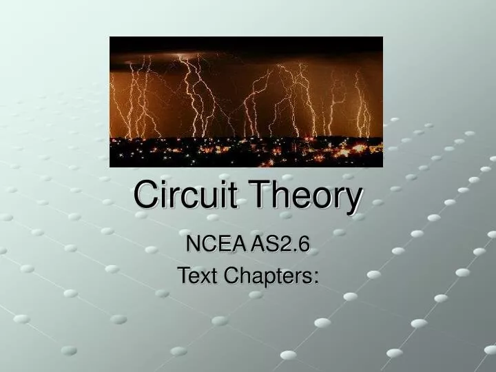
Circuit Theory. NCEA AS2.6 Text Chapters:. Electric Current. A flow of electric charge is called an electric current. Current I is measured by the rate at which electric charge flows Current = charge/time I = Q/t Unit: Ampere (Amp) A So 1A=1Cs -1

E N D
Circuit Theory NCEA AS2.6 Text Chapters:
Electric Current • A flow of electric charge is called an electric current. • Current I is measured by the rate at which electric charge flows • Current = charge/time • I = Q/t • Unit: Ampere (Amp) A • So 1A=1Cs-1 • Current direction is defined as the direction of positive charge flow.
Voltage • Current will only flow continuously if there is a closed circuit. • To get the charges to flow, they need to experience the force of an electric field. • To set up a field, we apply a voltage or potential difference to the circuit.
Voltage • A voltage V is a measure of the difference in potential energy of the charge between two points in a circuit. • Voltage=Energy/Charge • V=E/Q • So 1V=1JC-1 • A voltage can be positive or negative. ie energy gain or energy loss.
Resistance • All materials have a certain amount of electrical resistance R. • This inhibits the flow of charge and uses up the charge’s energy. • A material with very high R is called an insulator. • A material with very low R is called a conductor. • Resistance is measured in Ohms W.
Resistance • Resistance is directly proportional to Length. Longer = more resistance…… • Resistance is inversely proportional to the cross-sectional area. Thicker = less resistance • Resistance is directly proportional to the resistivity rof the material • In summary: R=Lr/A
Ohm’s Law • Current, voltage and resistance are linked by Ohm’s Law: V=IR • This applies only to conductors that have constant resistance. • Examples of non-Ohmic conductors include diodes, lamps, thermistors and LDRs.
Parallel Series Series and Parallel • If the components are linked one after the other they are in series. • If they are linked alongside each other they are in parallel
Meters • Ammeters measure current. • Connected in series so that all the charge flows through them • low R so that they do not use up the energy of the charge. • BE CAREFUL – Ammeters are easy to damage. • Voltmeters measure voltage. • Connected in parallel with the component they are measuring the voltage drop/gain across. • High R so that they do not draw too much current away from the circuit.
Combining Resistors • When connected in series, the total resistance RTis the sum of the individual resistors: • RT=R1+R2+R3…. • This has the effect of increasing the resistance of the circuit. • When connected in parallel, the total resistance is found by adding reciprocals…. • 1/RT= 1/R1+1/R2 +1/R3…. • This has the effect of reducing the total resistance of the circuit
4.5V 9.0V 4.5V Circuit Theory • Series Circuits: • Current must be the same everywhere as there is only one path for electrons to take. • Voltage must be shared by all resistors
2A 4A 9V 9V 9V 2A Parallel Circuit Theory • Parallel Circuits: • Current can split to go down either pathway • Each resistor gets all the energy the charge is carrying so voltage across each is the same
Internal Resistance • Even components like batteries and meters have resistance. • This means that even though a battery is supposed to supply 9V for example, what you get across it’s terminals may be less if you try and draw a large current from it. The battery’s resistance uses some of the energy.
R1 Vs R2 Vout Potential Dividers • Used to control voltage of parts of a circuit • Works great as long as the load resistor is large compared to divider resistors. (Why??) • Vout= R2/(R1+R2)xVsource
Power • Power = Energy/time • However V=E/Q & I=Q/t so combining them: • P = VxI = E/QxQ/t = E/t • Power is measured in Watts W • By substituting Ohm’s Law into the power equation, it can also be written as: • P=I2R or P=V2/R • This shows that the higher the current the more power dissipated as heat.
Electrical safety • 1mA is the maximum safe current the human body can take. • 100mA probably fatal • R(dry skin)=10kW • If 10V applied, I=1mA (safe) • If 240V applied I=24mA (hmmm) • R (wet skin)=1.2kW • If 240V applied I=200mA (R.I.P)