Download
1 / 26
260 likes | 510 Views
Understand the fundamentals of electric circuits, including resistors, Ohm's law, circuit analysis methods, and Kirchhoff's laws. Learn about circuit models, mathematical techniques, and circuit element construction.

E N D
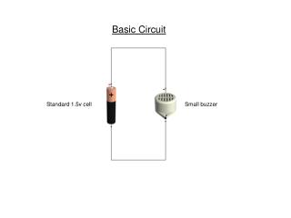
Sensors Technology – MED4 Basic circuit theory Lecturer: Smilen Dimitrov
Introduction • The model that we introduced for ST
Introduction • We have discussed • The units of voltage, current and resistance, in terms of electric circuits • The definition of an elementary electric circuit • Ohm’s law
Resistors • Construction of resistors • Different sizes for different power ratings • As far as construction of resistors goes, generally we can discern • Carbon Composition Resistors • Film Resistors • Carbon Film Resistors • Metal Film Resistors • Metal Oxide Resistors • Wire Wound Resistors
Resistors – color code • Ratings of resistors – written as color code
Basic circuit theory • Electrical circuit is a mathematical model that approximates the behavior of an actual electrical system. Circuit theory [consists of] models and mathematical techniques • Circuits (also known as 'networks') are collections of circuit elements and wires. • Electric circuits will be considered as graphs of two types of elements: nodes and branches. The branches, which are electric components like resistors and voltage sources, connect the nodes, which can be viewed as representatives of voltage potentials. • Circuit analysis is concerned with the computation of voltages and currents in a circuit for a certain excitation. There are various methods for equation formulation for a circuit. These are based on three types of equations found in circuit theory: • equations based on Kirchhoff's voltage law (KVL), • equations based on Kirchhoff's current law (KCL), and • branch constitutive equations.
Basic circuit theory • Solving a set of equations that represents a circuit is straightforward, if not always easy. However, developing that set of equations is not so easy. • The two commonly taught methods for forming a set of equations are the node voltage (or nodal) method and the loop-current (or mesh) method.
Basic circuit theory • Conventions – schematics • While analysing a state of a circuit, one also writes the direction of current and the polarity of voltage in a schematic
Basic circuit theory • Marking voltage • Technical and real direction of current
Basic circuit theory • Active and passive convention: the elements within a circuit will either: control the flow of electric energy or respond to it. • Open and Closed Circuits • 'Shorting' an element • Kirchhoff's laws are expressions of conservation laws: in physics, a conservation law states that a particular measurable property of an isolated physical system does not change as the system evolves. A partial listing of conservation laws that are said to be exact laws, or more precisely have never been shown to be violated.
1st Kirchhoff (current) law - KCL • Statement of the law of conservation of charge – “what goes in, must go out” • Or in particular – the sum of currents going in and out of a given node, is always equal to zero.
2nd Kirchhoff (current) law - KVL • Statement of the law of conservation of energy • The directed sum of the voltages (electrical potential differences)around a circuit (loop)must be zero. • Sum of voltages around every closed loop in the circuit must equal zero. A closed loop has the obvious definition: Starting at a node, trace a path through the circuit that returns you to the origin node. • An element's voltage enters with a plus sign if traversing the closed path, we go from the positive to the negative of the voltage's definition.
Ohms law and equivalence principle (Thevenin) • Ohms law here is the branch equation for a resistor: • Equvalence principle - Thevenin theorem – for resistive circuits, it is possible that circuits are represented through an equivalent circuit – a ”black box”
Measurement • Voltmeter is connected ”across” two points, ampermeter is connected ”through” a point
Elementary electric circuit • Simplest to solve using circuit theory: • Output voltage is simply equal to input voltage !
Series connection – the voltage divider • Our basic circuit in this course.
Series connection – the voltage divider • Our basic circuit in this course. The input voltage E is divided in two output voltages U1 and U2 The output voltage U2 is the input voltage E, divided by
Equivalent resistance of series connection • What does the power supply E ”see”? • The equivalent resistance for resistors in series is, as a value, always dominated by the biggest resistor in the sum
Parallel connection – current divider The input current I is divided in two output currents I1 and I2 -> The output voltage is the same as the input voltage !
Equivalent resistance of parallel connection • What does the power supply E ”see”? • The equivalent resistance for resistors in parallel is, as a value, always dominated by the smallest resistor in the parallel combination.
Combined connection To solve the circuit (find all the currents and voltages, we must set a system of 6 equations, using Kirchoff Laws and brach equations (Ohms law). The output voltage will be:
Combined connection Easier way to solve the circuit: Find equivalent parallel resistance And solve a voltage divider.... The output voltage will be:
Combined connection • Important – when Rih is almost infinite; simulates a connection of a voltage divider to the data acquisition (Arduino)!
Analysis methods • Just a mention of two analysis methods for solving complicated circuits: • Node Voltage Method (Nodal analysis) • Loop Current Method (Mesh current analysis)