Download
1 / 40
420 likes | 618 Views
Computer-Generated Pen-and-Ink Illustration. Georges Winkenbach, David H. Salesin. Why Pen-and-Ink?. Can convey information better by omitting extraneous detail (ex, medical & hardware manuals) Less storage than photorealistic images, and more easily reproduced and transmitted

E N D
Computer-Generated Pen-and-Ink Illustration Georges Winkenbach, David H. Salesin
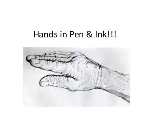
Why Pen-and-Ink? • Can convey information better by omitting extraneous detail (ex, medical & hardware manuals) • Less storage than photorealistic images, and more easily reproduced and transmitted • Ideal for outlines, tones and texture. • Blend nicely with text.
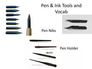
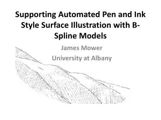
Basics of Pen-and-Ink Illustration-Strokes • A thin stroke can give a washed-out appearance; a thick stroke can detract from the details • Vary the pen position • Strokes must look natural; the thickness of a line should vary along its length • Wavy lines are good
Basics-Tones and texture • The tone is achieved by a combination of strokes. • Strokes can convey both tone and texture • Use equal weight and spacing of lines to create tones • Correct arrangement of tones among adjacent regions is important • Use of indication
Basics-Tones and texture Force tone by enhancing contrast or shadows to disambiguate objects • The character of strokes is important: • Crisp, straight lines are good for glass • Horizontal surfaces should be hatched with mostly horizontal lines • Absence of detail indicates glare • Sketchy lines are good for old materials; careful stippling is good for new material
Basics-Outlines • Use outlines to convey texture (crisp lines for hard objects) • Use outlines to bring one object forward in the scene • Using indication for drawing outlines is important
Computer-generated pen-and-ink illustration • Two fundamental differences from traditional graphics rendering pipeline: • Dual nature of strokes • Need to combine 2D and 3D information • Stroke density • 2D adjacent regions • Level of contrast
Non-photorealistic Rendering Pipeline • Standard pipeline (unchanged) • Model • Assignment of texture (strokes) • Lighting model (phong model) • Visible surface algorithm (BSP) • Shadow algorithm • Differences from the standard pipeline: • Maintaining 2D spatial subdivision • Rendering of texture and tone (strokes) • Clipping (stroke base) • Outlining (boundary & interior)
Rendering process • Compute visible surfaces and shadow polygon • Project polygon to build 2D BSP tree and planar map • Visible surface is rendered • Procedural texture for each surface • Clip strokes • Draw outlines
Strokes • Nib moving along a basic straight path • Use waviness and pressure function to add character to the strokes
Stroke textures • Stroke texture – a collection of strokes used to produce texture and tone • Prioritized stroke texture: • Strokes of highest priority are drawn first • Continue until the proper tone is achieved
Resolution Dependence • Existing drawing program do not scale well when printed at different sizes or resolution • Pixel replication yields aliasing artifacts • Drawing same stroke at higher resolution yields overall lighter illustration • Reduction yields large black mass of overlapping strokes • Prioritized stroke textures do not suffer from these problems!!
Indication • Indication lends economy to an illustration • Suggest texture without drawing every stroke • Hard to do, paper suggests semi-automated method • W(x, y) = (a + b*distance((x, y), l))^(-c)
Expression texture with outline • Associate each stroke texture with boundary or interior outline texture
Minimizing outline • Outline is omitted in the presence of sharp changes in tone, and added in the absence of tone changes
Accented outlines for shadowing and relief • Thickened lines can provide cues about the 3D aspects of a scene • Edges that cast shadows are rendered with thickened lines
Dependence of viewing direction • Viewing direction should be taken into account • Each stroke texture is associated with BRDF • describes outline features in terms of light and viewing directions.
Conclusion • Traditional pen-and-ink illustration can be used to communicate visual information effectively • Showed a large number of these techniques can be incorporated as part of the rendering pipeline • Introduced prioritized stroke texture to allow resolution-dependent rendering
Computer-Generated Pen-and-Ink Illustration of Trees Oliver Deussen, Thomas Strothotte Presented by Johnny Chang
Traditional Illustration of Trees • Tree skeleton is drawn up to the second branching level with silhouette lines and crosshatching on the stem surface. • Use abstract lines or collection of small objects to draw foliage.
Traditional Illustration of Trees • Three areas of foliage: • Top of the tree- visualized by few details and its outline. • Half shadow area – more details are drawn to achieve gray level. • Shaded area
Synthetic Illustration of Trees • Stem skeleton is represented by silhouette lines and crosshatching • Different types of leaves and illustration styles for abstract leaf representation • Drawing of leaf is modulated by three areas: top, half and deep shadow.
Automated Illustration • Create 3D tree model, using xfrog • Store geometry of the tree skeleton • Store leaves as particles each with a position and a normal vector • Draw the trunk and branches (silhouette lines+cross-hatching) • Draw foliage using depth difference algorithm
Drawing the tree skeleton • Apply analytical silhouette algorithms (Markosian, Rakarand Cohen) • Skeleton is shaded to find dark regions. Dark regions are crosshatched in the illustration. • Use gray scale to determine stroke size. • Direction of the strokes affected by normal vector of the geometry.
Drawing the foliage • Each leaf is represented by the outline of an abstract drawing primitives • Position is determined by 3D leaf position. • Size of primitive is controlled by the user
Depth Differences • Use depth-buffer to determine the outline of objects. • Use zero order derivatives for determining lines • The outline of a primitive is drawn if depth difference is above a threshold
Depth Differences • Depth z in the camera coordinates is determined from a depth value d z1 z0(d1 - d0)/(z1 - z0) Z= d -(z 1+z0)(d1 - d0)/2(z1 - z0) -(d 1+d0)/2
Abstract Drawing Primitives • 9 polygons was generated to represent leaves from different views • Normals were used to interpolate the shapes of the leaves
Level of Abstraction • Visual level of abstraction can be supported by scaling the primitive size • Scale factor: r=w(d/s)+(1-w) , w [0..1]
Conclusion • A Framework for pen-and-ink illustration of trees • Tree skeleton is represented by silhouette lines and crosshatching in dark areas. • Foliage is drawn using abstract drawing primitives. • An interpolation scheme to adapt the form of the primitives to the normal vector of the leaves • Depth differences are used to determine what part of the primitives is drawn.