Download
1 / 42
420 likes | 540 Views
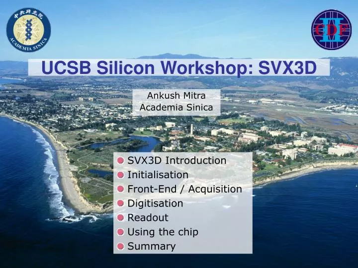
UCSB Silicon Workshop: SVX3D. Ankush Mitra Academia Sinica. SVX3D Introduction Initialisation Front-End / Acquisition Digitisation Readout Using the chip Summary. 6 Years old with no update. Warning!!!!!!.

E N D
UCSB Silicon Workshop: SVX3D Ankush Mitra Academia Sinica • SVX3D Introduction • Initialisation • Front-End / Acquisition • Digitisation • Readout • Using the chip • Summary
6 Years old with no update Warning!!!!!! This talk is based on the chip manual, other (sparse!) chip documents and my intuition UCSB Silicon Workshop: SVX3D
SVX3D Introduction UCSB Silicon Workshop: SVX3D
SVX3D reads out the charge from the Silicon sensor Each chip (+hybrid) is attached to the Silicon sensors There are ~5,000 chips in SVX-II Where is the SVX3D? UCSB Silicon Workshop: SVX3D
SVX3D 7.56MHz (132ns period) FECLK 53MHz (19ns period) BECLK 47 Deep Analog Pipeline X 128 128 Analog Integrators Digitisation & Sparsification 128 Silicon Strips 53 MBytes/s Data Out Analog (Front End) Digital (Back end) • “2 Chips” in one • Analog Front End • Digital Back End • Many programmable features • Can read out N and P type Silicon strips • Multiple chips can be daisy-chained UCSB Silicon Workshop: SVX3D
SVX3D Daisy Chain Bus 0 – Bus 7 + OBDV Chip Control Lines • TNBR/BNBR allow inter-chip communication • Has multiple roles • Data Lines and Control lines share a common bus • Data Lines have multiple roles UCSB Silicon Workshop: SVX3D
Acquisition Acquisition Acquisition Acquisition Initialisation Digitisation Readout Digitisation Readout Initialisation Chip Modes • Initialisation : Front-End & Back-End • Setup SVX3D • SET DEFAULTS in SVXDAQ • CONFIG in Run Control • Acquisition : Front-End • Collect charge from the sensor and store it on the pipeline • Digitisation : Back-End • Digitise the channels • Readout : Back-End • Send data out of chip SVX3D can collect charge and digitise simultaneously Front End Back End time UCSB Silicon Workshop: SVX3D
Initialisation UCSB Silicon Workshop: SVX3D
Initialisation: Single Chip • SVX3D has many programmable features • Need to initialise chip before it can be used for data taking • Sent as a 197 bit serial bit stream • Data is sent in through TNBR and clocked on FECLK • Use CALSR to latch in shadow register BNBR TNBR 197 Bit Serial Shift Register 69 128 FECLK CALSR Shadow Register Test Inputs Adjustable Chip Parameter UCSB Silicon Workshop: SVX3D
Initialisation: Daisy Chain • In daisy chain, TNBR/BNBR link shift registers of all chips together • For a daisy chain of chip, send Nchip x 197 bits • So first bit sent ends up in last chip in chain (chip 0) Chip 3 Chip 2 Chip 1 Chip 0 UCSB Silicon Workshop: SVX3D
Read Neighbours (163) Read All (164) ADC Ramp Dir (165) ADC Comp Dir(166) Ramp Slope Trim (167-174) Threshold (175-182) Counter Modulo (183-190) RDriver (191-193) ADC Ramp Pedestal (194-197) Channel Mask (1-128) CAL Direction (129) FE Polarity (130) Bandwidth (131-133) Pipeline Depth (134-139) ISEL (140-150) Readout Order(151) Chip ID (152-158) DPS (159) Bias Ratio (160) Driver Bias (161) Last chip (162) Initialisation: What can be set UCSB Silicon Workshop: SVX3D
Front End / Acquisition UCSB Silicon Workshop: SVX3D
Front End • All 128 channels acquire charge simultaneously • Each channel implements same circuit • Collected charge is transferred onto analog pipeline X128 for 1 chip Integrator Analog Pipeline UCSB Silicon Workshop: SVX3D
Integrator reset: Controlled by PARST Only applied in abort gap Charge on cf Bunch train collision time Front End: Integrator During bunch crossings, charge on integrator capacitor is allowed to build up cf Charge from sensor Test Charge: Polarity set by CALDIR Bandwidth set by initialisation bits UCSB Silicon Workshop: SVX3D
Acquisition: Pipeline c47 47 Cells in pipeline • 42 cells for L1A latency • 4 L1A buffers • 1 Reference capacitor (only filled in abort gap) Pipeline logic controls pipeline switches c2 c1 Initialisation bits set Pipeline operating currents, polarity and pipeline depth cc This capacitor store the charge on cf from previous bunch crossing Only difference of charge on cf and cc is transferred to pipeline cell cn Write Amp Read Amp UCSB Silicon Workshop: SVX3D
Acquisition: Pipeline logic • All pipeline capacitor cells are filled in a round-robin fashion Þ Advanced by FECLK • If a L1A is received • pipeline cell n-(L1 latency) is reserved • This cell is skipped over and only returned to pipeline after it is digitised (done by PRD2 signal) • Only 4 cells can be tagged (4 L1 buffers) • During abort gap, pipeline cell 47 is set Tagged Cell Write pointer Pipeline circular buffer UCSB Silicon Workshop: SVX3D
Back End / Digitisation UCSB Silicon Workshop: SVX3D
Digitisation: Subtraction of Pedestal c47 • PRD1 used to transfer charge from pipeline • If READOUT ORDER=0 • First PRD1 puts cell 47 on cs (pedestal) • Second PRD1 reads out cn (signal+pedestal) • pedestal – (signal+pestal) transferred • For READOUT ORDER=1, the order is reversed c2 c1 Write Amp cs Read Amp To ADC UCSB Silicon Workshop: SVX3D
Conversion of analog charge to digitised value is performed by Wilkinson-type ADC RAMP-RST starts a common voltage ramp CNTR-RST starts a common 8 bit counter Incremented by both edges of BECLK When voltage-ramp=VIN,m comparator fires Latch locks current counter value Digitisation: Wilkinson ADC VIN3 VIN2 VIN1 UCSB Silicon Workshop: SVX3D
From the initialisation, many of the ADC parameters can be adjusted Direction of ramp set by ADC RAMP DIRECTION Ramp Reference is set by Ramp Pedestal + ADC RAMP PEDESTAL (can be +ve or –ve) Slope of ramp can trimmed by ADC SLOPE TRIM Comparator can trigger off rising or falling edges: Set by ADC COMPARATOR DIRECTION Maximum value of counter is set by COUNTER MODULO Bias current of comparator and voltage ramp op-amp can be adjusted by BIAS RATIO V Start counter 0 signal level Digitised value signal level Ramp Pedestal Ramp Reference t Latch counter Digitisation: ADC Setting Position of start counter determines where 0 ADC counts sits UCSB Silicon Workshop: SVX3D
Method to calculate common mode pedestal in real time by delaying start of counter. DPS works if: Low hit occupancy Uniform pick up across all 128 channels Once N comparators have fired, counter starts Channels near pedestal will fire first VThreshold set externally via resistor External resistor set to 7kW Þ 35 Channels need to fire CDF Note 4852 Digitisation: Dynamic Pedestal Subtraction All channels are capacitively coupled UCSB Silicon Workshop: SVX3D
Digitisation: Threshold & Sparsification • If in NN or Sparse mode, channels with ADC value > Threshold are read out • If Threshold > COUNTER MODULO: No channels read out • In NN mode adjacent channels are read out • If channel 0 or 127 are hit, neighbour information is passed via TNBR & BNBR respectively • Before Readout, each hit channel is stacked into asynchronous FIFO for fast readout • ~600ns needed for FIFO to collapse UCSB Silicon Workshop: SVX3D
Front End / Readout UCSB Silicon Workshop: SVX3D
Readout: Data Format • Data is transmitted in 1 Byte chunks. • Always accompanied with Odd-Byte-Data-Valid (OBDV) Signal UCSB Silicon Workshop: SVX3D
Readout: Multiple Chips • Priority of chip readout is passed down via TNBR/BNBR lines • In this example, Chip 3 is read out first and then the others • First channel, first chip and last chip, last channel are always read out • Q: How does the chip do this ? Not mentioned in chip manual Readout token passed along chip chain Chip 3 readout first Chip 0 readout last UCSB Silicon Workshop: SVX3D
Experience with SVX3D UCSB Silicon Workshop: SVX3D
Chip Features During detector commissioning, a number of features were found • Keep Alive • Every 270ms, PRD2 and BE Clock has to be sent, if no other command has been sent • No keep alive: chip goes into high current state and trips off • Mini Digitise • At end of readout, send extra BE Clocks (& maybe other signals?) • Why? Works better if you do it (Tom Zimmerman – SVX3D father) • Abort Digitise disabled • Was implemented to stop digitisation early. • Found to make chip go into a high current state. Now SRC & FIB protect against this • Need to reinitialise from time to time • 1 chip consumes 80-100mA on AVDD • Sometimes AVDD drops 1 chip of current spontaneously during data taking • Need to reinitialise chip chain (HRR) UCSB Silicon Workshop: SVX3D
CAP-ID is sometime indicator an impending AVDD2 failure Behaviour can be reproduced by removing AVDD2 bond Chips draws power parasitically from DVDD “Finger” connects hybrid and chip via silver epoxy joint Some AVDD2 Failures do recover Observed Symptoms Loss of communication to chip front-end Increase in DVDD current Chip chain broken after affected chip Failure observed after beam incidents (or when ladder temperature changes) epoxy finger bonds Chip Problems: AVDD2 Failure UCSB Silicon Workshop: SVX3D
53MBytes/s Data Out Digital (Back end) Digitisation & Sparsification 47 Deep Analog Pipeline Analog (Front End) 128 Analog Integrators 128 Silicon Strips SVX3D Summary • All Silicon ladders readout by SVX3D chip • Integrated Analog Front-End and Digital Back-End • Dead-timeless: • Can collect charge and digitise simultaneously • Honeywell Rad-Hard CMOS 0.8mm Process • 4 MRads with Co60 Source • 15 MRads with 55MeV Proton Source • Fast: Capable of running at 132ns clock rates • Dynamic Pedestal Subtraction • Subtracts common mode noise • Sparsification • Removes channels below programmable threshold • Reduces data-rate and readout time UCSB Silicon Workshop: SVX3D
Backup UCSB Silicon Workshop: SVX3D
SVX3D Floor plan A number of lines have multiple roles Top Neighbour Chip control lines Digital Power 128 Inputs Calibration Voltage 8 Bit Data Bus + OBDV Analog Power Bottom Neighbour UCSB Silicon Workshop: SVX3D
Acquisition: Pipeline Timing • FECLK clock used to advance pipeline • FECLK • coincides with beam-crossing • Difference of cf and cc is transferred to pipeline cell cn • FECLK • Advance pipeline • Pipeline cell cn+1 is reset • cc stores charge from previous bunch crossing UCSB Silicon Workshop: SVX3D
Initialisation: SVXDAQ Chip ID (152-158) Threshold (175-182) Pipe Depth (134-139) Ramp Trim (167-174) Bandwidth (131-133) Counter Mod (183-190) Ramp Pedestal (194-197) UCSB Silicon Workshop: SVX3D
Initialisation: SVXDAQ Predefined settings for polarity Pipe Sel (130) Cal Dir (129) Readout Order (151) Comp Dir (166) Ramp Dir (165) Last Chip (162) Readout Mode (163,164) UCSB Silicon Workshop: SVX3D
Initialisation: SVXDAQ • Calibration Masks for each channel • Set bit to 1 for channel to be readout for calibration UCSB Silicon Workshop: SVX3D
Initialisation: SVXDAQ • ISEL Bits (140-150) • Program currents for FE Op-Amps UCSB Silicon Workshop: SVX3D
Initialisation: SVXDAQ • Driver Com Mode (161) • Bias Ratio (160) • Dynamic Threshold (159) • Resistor Driver (191-193) UCSB Silicon Workshop: SVX3D
Readout Driver Com Mode adjusts VRef • Data is output via tri-stated 8 bit parallel bus • Can operate in Current driver or Resistor driver mode • The resistors in the driver are switch on/off via the RDriver values • MSB: Adds 6.3mA • Mid Bit: Adds 3.3mA • LSB: Adds 1.7mA UCSB Silicon Workshop: SVX3D
SVX3D Radiation Hardness test Bare chip noise vs rad Cap dep. noise vs rad • Rad test with • Co60 source up to 4MRad • 55MeV proton beam to 15MRad Chip noise increases (30+3.2*Cap) electrons per Mrad UCSB Silicon Workshop: SVX3D
Ä I Wire Motion B Chip Problems: Wirebond Resonance • Observed loss of data & power to Z sides of ladders • Found to correlate with high trigger rates • Failure due to wirebond resonances • Wires orthogonal to magnetic field • Wires feels Lorentz force during readout • If frequency is right, wires resonate and break More details in resonance talk!! UCSB Silicon Workshop: SVX3D
Chip Noise @ 8fb-1 • Layer0 of SVX has chips with smallest radius from IP • With init chip noise 1,600e and 18.3 pF load, the estimation is 5.5% noise increase per MRad • Expect 17% of noise increase with 8fb-1 • The S/N degradation will have large contribution by sensor shot noise. Expectation at 8fb-1 UCSB Silicon Workshop: SVX3D
How many chips • SVX • L0: 2 Rf & 2 Rz Þ 4 Total • L1: 3 Rf & 3 Rz Þ 6 Total • L2: 5 Rf & 5 Rz Þ 10 Total • L3: 6 Rf & 4 Rz Þ 10 Total • L4: 7 Rf & 7 Rz Þ 14 Total • ISL • Each Ladder has 4(Rf) + 4(Rz) Þ 8 chips • Each DAQ Layer is 2 ladders Þ 16 chips • L00 • Narrow: 1 chip • Wide: 2 chips UCSB Silicon Workshop: SVX3D