Download
1 / 43
520 likes | 1.66k Views
Transformer. Agus Purwadi, Qamaruzzaman & Nana Heryana. Laboratorium Penelitian Konversi Energi Elektrik Institut Teknologi Bandung. Transformer. A transformer is a device that convert ac electric energy at one voltage level at another voltage level. Definition.

E N D
Transformer Agus Purwadi, Qamaruzzaman & Nana Heryana Laboratorium Penelitian Konversi Energi Elektrik Institut Teknologi Bandung
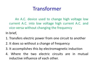
Transformer A transformer is a device that convert ac electric energy at one voltage level at another voltage level. Definition
Transformer are important to modern life 1. Why • Thomas A. Edison (1882) Power Distribution System : New York-USA ; 120 Vdc Problems : Losses & Voltage Drop = inefficient Example : Inefficient
High Voltage Efficient
Transformer are important to modern power system LV HV High Voltage Low voltage Inefficient Efficient
Real Application on Power System 20 kV/380 V 380 V/20 kV
Frequency • Power Frequency , 50/60 Hz • Radio frequency, > 30 kHz Teknik Tenaga Elektrik • Power Transformer • Instrument Transformer Transformer
3. The Ideal Transformer Turn ratio a
The Ideal Transformer Turn ratio a
The Ideal Transformer In term of phasor quantities
Power in ideal Transformer Power input Power input ideal Turn ratio equation
Power in ideal Transformer Active power reactive power Apparent power
Evaluasi • Untuk memahami konsep trafo ideal berikan ke mahasiswa, contoh sederhana misalnya : • Cara mendapatkan tegangan sekunder y volt jika tegangan primernya x volt. • Arus sekunder b ampere pada tegangan y volt, cari arus primer a ampere pada tegangan X volt. • Ambil nilai x dan y yang bedanya sangat besar • Soal pada sistem 1 fasa dulu saja.
Impedance Transformer Impedance = ratio of the phasor voltage across it ti the phasor current
Theory of operation of real single-phase transformers The basis transformer operation can be derived from Faraday’s law Flux linkage
EMF equation of a transformer Faraday law of electromagnetic induction RMS Value
Transformer Losses • Copper (I2R) losses • Eddy current losses • Hysteresis losses • Leakage flux
The equivalent circuit of a transformer the model of a real transformer
Test on transformers • Open-Circuit Test • Result : VOC IOC POC
Open-Circuit Test Result Conductance of the core-loss resistor Susceptance of the magnetizing inductor Admittance Magnitude admittance
Open-Circuit Test Result Power Factor Power Factor angle Admittance
Test on transformers Short-Circuit Test Result : VSC ,ISC ,POC
Short-Circuit Test Result Series impedance Power Factor of the current Lagging - Current angle (-),Impedance angle (+) Therefore,
Short-Circuit Test Result Series impedance Admittance
2.2 The equivalent circuit impedances of a 20 kVA, 8000 / 240 V, 60 Hz transformer are to be determined. The open circuit test were performed on the primary side of the transformer, and the following data were taken : Open-circuit test (on primary) Shots-circuit test (on primary) VOC = 489 V IOC = 2,5 A POC = 240 W VOC= 8000 V IOC = 0,214 A POC = 400 W Test
The per-unit system of measurement In single-phase system :
Voltage Regulation & Efficiency Voltage Regulation Efficiency
Autotransformer Step-down autotransformer
Power rating -autotransformer SIO =Input and Output apparent powers SW = apparent power in the transformer windings Example For example, a 5000 kVA autotransformer connecting a 110 kV system to a 138 kV system would have an NC/NSE turn of ratio of 110 : 28. Such an autotransformer would actually have windings rated at :
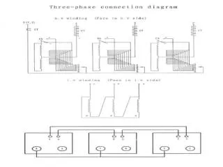
Three-phase transformer A three-phase transformer bank composed of independent transformer A three-phase transformer wound on a single three-legged core
Three-phase transformer connections • Wye-wye (Yy) • Wye-delta (Yd) • Delta-wye (Dy) • Delta-delta (Dd)
Test A 50 kVA 13.800 / 208 V, Dy distribution transformer has a resistance of 1 percent and reactance of 7 percent per unit. • What is the transformer’s phase impedance referred to the high-voltage side? • Calculate this transformer’s voltage regulation at full load and 0,8 PF lagging, using the calculated high-side impedance. • Calculate this transformer’s voltage regulation under the same conditions, using the per-unit system.
Instrument transformers • Potential transformer (PT) • Current transformers (CT)