Download
1 / 39
390 likes | 540 Views
Picture. Site Context. Lake Geneva, Switzerland Surrounded by the Alps 20 °C mean temperature in summer Annual snow fall – 30in. Site Analysis. 10,000 sq. ft. footprint Flat site Excellent gravel Clear view to the lake Easily accessible by two roads. Topsoil. Lake Geneva. Good gravel.

E N D
Picture Site Context • Lake Geneva, Switzerland • Surrounded by the Alps • 20°C mean temperature in summer • Annual snow fall– 30in
Site Analysis • 10,000 sq. ft. footprint • Flat site • Excellent gravel • Clear view to the lake • Easily accessible by two roads Topsoil LakeGeneva Good gravel Water table
A Design Genesis
EIFS Cladding Exterior Cladding A Reflective Glass Façade System
Live loads Corridor 1st floor (classrooms) 5 kN/m2 Auditorium 5 kN/m2 Auditorium with fixed seating 4 kN/m2 Classroom, seminar room, lab, office 3 kN/m2 Snow0.75 kN/m2 Wind 0.9 kN/m2 Earthquake max. 0.05% of gravity loads 1 kN/m2 = 20.48 lb/sf 1 m = 3.28 ft 1k Structural System Picture Overview E
Groundwater Table Structural System Picture Foundation E Waterproofing Retaining wall Foundation
D=14mm D=10mm Structural System Picture Walls and Columns E
Structural System Picture Auditorium E
Structural System Picture Auditorium E
Structural System Picture Auditorium E
Max. deflection –15.7mm Structural System Picture Concrete Slabs E
Structural System Picture Lateral Load Resisting System E
Structural System Picture Lateral Load Resisting System E Shearwall:
Construction Issues Picture Objectives C • Budget - $5.5M • Timeline – 1 year • Faster • Cheaper • Life cycle cost savings
Construction Issues Picture Site Plan C • Bonus double access roads • Can divert traffic if needed and use the other side of the road • Mobile crane
Hauling Truck Pump Truck Construction Issues Picture Equipment C Based on capacity and availability Capacity -1.54cubic meter. Boom – 54m Reach curve
Construction Issues Sequencing C
Construction Issues Picture Schedule Milestones C Start Substructure complete Mar 1, 2015 May 4, 2015 Sep 27,2015 Framing complete Dec 13,2015 End
Construction Issues Picture Schedule Analysis C • Project Duration – 9 months • Resource allocation considered • Snow season- December 15th to February 15th • Steel procurement lead time
Construction Issues Picture Cost Estimate C Total Project Cost = $5.29 M (3.38 M in 2001)
Construction Issues Picture Cost Analysis C EIFS vs Concrete Panels:
Construction Issues Picture MEP Issues C • Concerns • Head Room – Floor to floor heights? • Location of MEP room • Choice of a centralized vs distributed system
Construction Issues Picture MEP Design C • Cores used for risers with diameter of 24” • Distribution at center brings used air down • Fresh air distributed through the lateral cores. • Duct sizes • typical rooms 14” • auditorium 18”
Construction Issues Picture Floor Systems Comparison C • Raised Floor System – Benefits and Disadvantages • Improved efficiency • More effective • Allows great deal of flexibility • 1.25 times cost of conventional system
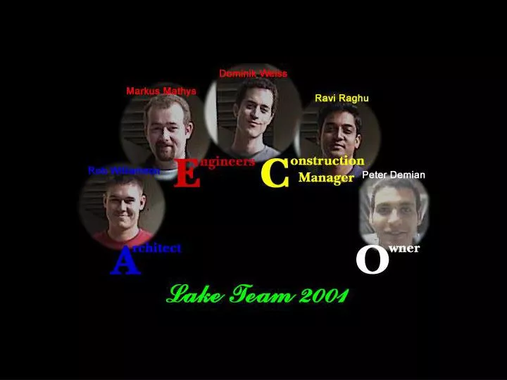
Team Dynamics AE C Case 1: Floor heights iteration C E A
Team Dynamics AE C Case 1: Floor heights iteration C E A
Team Dynamics AE C Case 1: Floor heights iteration C E A
Team Dynamics AE C Case 1: Floor heights iteration C E A
Team Dynamics AE C Case 2: Mechanical Room Location
Team Process AE C
Conclusion AE C Working together, we were able to design a building that: • Closely meets the program requirements • Functions well as a learning facility • Responds to the site • Has a fairly low-life cycle cost • Is adaptable to meet changing needs
Lessons Learned AE C • Early design commitments • Early consideration of MEP and structural systems • Cross-disciplinary design contribution • Synchronous communication • Common AutoCAD drawing
Acknowledgements AE C Renate Fruchter, Stanford University Mike Martin, U.C. Berkeley Humberto Cavalli, U.C. Berkeley David Bendet, MBT Architects Hansjörg Baumann, BauIng AG, Switzerland Bob Tatum, Stanford University James Bartone, Nielsen Dillingham Eric Horn, Webcor Builders