Download
1 / 3
30 likes | 117 Views
PhTiMes. Standard VME crate DTDC – Data driven TDC, VME A24D32 module based on the HPTDC chip. 32/64 dECL channels (25/100 ps resolution) MVME – standard VME CPU PhLoM – Phobos Logic Module Busy-free. 100 Mbps. MVME. PhLoM. DTDC. CC mCC L0 L1/ evN.

E N D
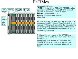
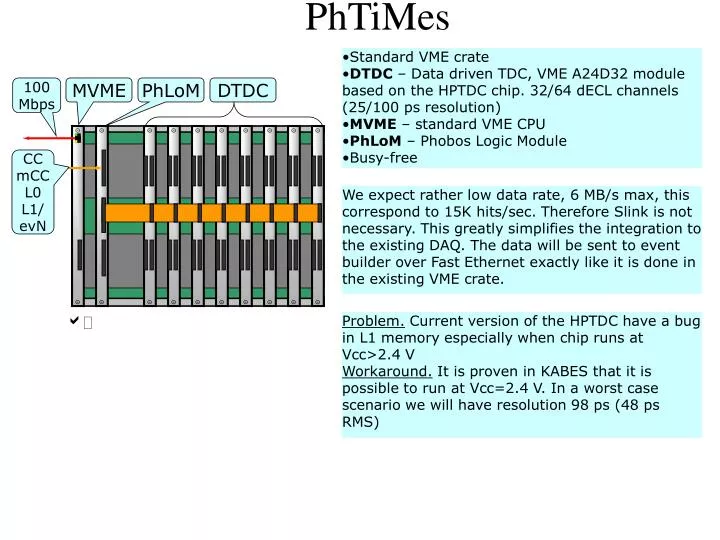
PhTiMes • Standard VME crate • DTDC – Data driven TDC, VME A24D32 module based on the HPTDC chip. 32/64 dECL channels (25/100 ps resolution) • MVME – standard VME CPU • PhLoM – Phobos Logic Module • Busy-free 100 Mbps MVME PhLoM DTDC CC mCC L0 L1/ evN We expect rather low data rate, 6 MB/s max, this correspond to 15K hits/sec. Therefore Slink is not necessary. This greatly simplifies the integration to the existing DAQ. The data will be sent to event builder over Fast Ethernet exactly like it is done in the existing VME crate. a Problem. Current version of the HPTDC have a bug in L1 memory especially when chip runs at Vcc>2.4 V Workaround. It is proven in KABES that it is possible to run at Vcc=2.4 V. In a worst case scenario we will have resolution 98 ps (48 ps RMS)
Triggering Search window 40 MHz RF, 36 ns Hits L1 settling time PhL1 • Triggering of the PhTiMeS • No Phobos L0. • Phobos L1 (PhL1) is synchronized with the RF and have constant delay relative to the triggering bunch crossing. • RF is not measured in the TDC. • Upon receiving of the PhL1 the PhTiMeS calculates a region of interest (ROI) by subtracting the ‘L1 Settling Time’ from the current clock position. Obviously, the width of the ROI should cover spread of the hits plus one clock. All hits from the ROI will be transferred to an L1 output buffer (circular buffer, 256 word deep). • Note. The maximum bunch filling of the RHIC is 112, in this case the distance between the possible bunch crossing is 3 RF ticks = 108 ns.
Interlaced Grounding 1 3 5 7 9 11 13 15 0 2 4 6 8 10 12 14 Fig. 1. Distribution of the ground between pairs in the twisted pair cable. • Easy installation: • Two existing cables combined together using adapter card which is plugged in to a TDC • Put additional 16 cables. Cost for 500 lines of 400 ns SpectraStrip 3M type 1700/34 length 300’ for $279 = $7132 Connectors. ($15+$2)*16 + $150 = $422 Total: $7600. Fig. 2. Small adapter card combining 2 interlaced cables to one normal socket