Download
1 / 32
320 likes | 445 Views
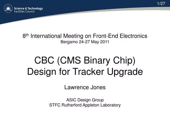
1/27. 8 th International Meeting on Front-End Electronics Bergamo 24-27 May 2011 CBC (CMS Binary Chip) Design for Tracker Upgrade Lawrence Jones ASIC Design Group STFC Rutherford Appleton Laboratory. 2/27. Overview of Talk Introduction Analogue Design Digital Design Test Results

E N D
1/27 8th International Meeting on Front-End Electronics Bergamo 24-27 May 2011 CBC (CMS Binary Chip) Design for Tracker Upgrade Lawrence Jones ASIC Design Group STFC Rutherford Appleton Laboratory
2/27 • Overview of Talk • Introduction • Analogue Design • Digital Design • Test Results • Conclusion • Acknowledgements
3/27 • CBC Introduction • - CBC is intended for use in the outer tracker of the SLHC with short strip detectors (2.5-5cm) • - The original LHC readout chip (APV25-S1) had an analogue non-sparsified readout architecture. • - For SLHC, a binary non-sparsified readout has been chosen as the target architecture for the CBC. • - This has the following advantages over a digital sparsified system. • - Simplifies readout architecture, simpler on-chip logic • - Occupancy independent data volume • - No ADC • - Lower power • - Can be emulated off-detector • - Simpler overall system • - Designed on IBM 130nm CMOS.
4/27 Preamplifier x 128 Gain Amplifier x 128 Programmable Offset Comparator x 128 Programmable Hysteresis Hit Detect Logic Pipeline RAM 128x256 Data Buffer 128 x 32 Output Shift Register CMS Binary Chip (CBC) Overview DC-DC Converter • 128 Channels • - preamp, postamp, comparator • Both polarities of signal • - designed for both electrons and holes • Binary Conversion • - programmable hysteresis, less than16ns time walk • Pipeline memory 256 deep • - 2 port RAM, no SEU immunity • Buffer Memory 32 deep • - pipeline address has hamming encoding • Programmable Biases • fully programmable through I2C with 8bit resolution • referenced to bandgap (provided by CERN) • LDO Regulator • - stand-alone block, can be used or not • DC-DC Converter • 2.5V to 1.2V, stand alone block • - provided by CERN • I2C Interface • SLVS I/O • - provided by CERN 2.5v 1MHz 1.2v PWR GND I2C I/O SDAO SDAI SCK SLVS I/O R/W Pointers Address Buffer 8 x 32 Pointer Sequencing and Readout Logic Programmable Voltage / Current Bias DOUT I2C Interface 40Mhz Trig Bandgap LDO 1.1v 1.2v
5/27 Front End Specification Detector Type: Silicon Strip (both n-on-p and p-on-n) Signal Polarity: both (electrons and holes) Strip length: 2.5 – 5 cm Strip Capacitance: 3 – 6 pF Coupling: AC or DC Detector leakage: up to 1 uA leakage current compensation Noise: less than 1000 electrons rms for sensor capacitance up to 5 pF Leakage noise: 400 electrons rms for 1uA leakage Overload recovery: normal response within ~ 2.5 us after 4 pC signal Power: ~ 500 uW / channel (for 5pF strips) Operating temp.: In experiment probably < -20C but will want to test at room temp. Power supply: 1.1 V (assumes front end supplied through LDO to get supply noise rejection) Gain 50 mV/fC Dynamic range: respond linearly up to 4fC Timewalk: less than16 ns for 1.25 fC and 10 fC signals with comp. thresh. set at 1 fC
6/27 CBC Front End • Preamplifier • -100fF feedback capacitor • - Selectable resistive feedback network absorbs leakage current • - 20ns time constant minimises effects of pile up • Postamplifier • - Designed for both electrons and holes • - Coupling capacitor removes leakage current shift • Programmable offset for trim • 8 bits 200mV range • Comparator • - Global Threshold • - Programmable hysteresis • - Selectable polarity
7/27 Front End Simulations Preamplifier Single feedback resistor for electrons T network for holes to increase headroom with leakage shift All Corners Ileak = 1uA Ileak = 0 -2fC to 8fC in 1 fC steps Ipaos2 Postamplifier Offset adjustable using programmable current through resistor 10 uA 0 uA All Corners 1.5fC
8/27 Post Amplifier Electrons - Current mirror biases feedback transistor. - Sources connect to Vplus As signal is negative going - Current programmable through bias generator Holes - Sources of current mirror connect to output since signal is positive going. - 1pF capacitor ensures gates track output to maintain linearity All Corners 2fC steps All Corners 2fC steps
9/27 Comparator Programmable hysteresis:
10/27 Hit Detection Logic . Mode 1 - A synchronised version of the input is passed through to the output (a). - If the pulse is too short it may be missed (b) Mode 0 - The comparator pulses are compressed or stretched to be one clock cycle in length (d,e) - The output from the Hit detection circuit feeds directly into the pipeline RAM.
11/27 Pipeline Architecture • Latency Register • defines separation of pointers • 256 clocks, 6.4us at 40Mhz • Pointer Start Logic • enables the Write/Trigger Counters • latency separation • Write/Trigger Pointers • 8 to 256 decoders • Latency Check • monitors counters • if difference ≠ latency then error • Pipeline/Buffer RAM • dual port • Buffer RAM configured as FIFO • Output Shift Register • - 140 to 1 parallel load and shift • Trigger and Readout Control • - decodes fast control (trigger input) • controls transfer from pipeline to buffer when triggered • monitors Up/Down Counter to check for data • sequences loading of shift register and shifting of data
12/27 SEU tolerant D-type flip-flop Transistors go tri-state if their input is corrupted Storage nodes p diffusion incorruptible 1 incorruptible 0 Storage nodes n diffusion
13/27 SEU tolerant Data Register (I2C) - Triple RAM Cells with voting circuit - Used in the I2C registers - Settable and resettable versions - Store the chip modes and bias settings
14/27 Present Status • March 2009 – Design Started • Process – IBM 130nm CMOS • Designers – Lawrence Jones, STFC • Mark Raymond, IC • Various Sub-blocks CERN • July 2010 – Design Submitted • February 2011 – Testing Started • May 2011 – Chip is Fully Functional
15/27 Test Results Provided by Mark Raymond, Imperial College
16/27 • CBC Test Results • One full data frame and the start of a second. • - 1fC of charge injected into one channel via an external capacitor • - Header consists of • 2 start bits “11” • 2 error bits – latency, full • 8 bit pipeline address • 128 channel data • - One full data frame showing charge injected through internal capacitors on every 8th channel • - Approximately 1.5fC 1st Header 128 bit Channel Data 2nd Header
17/27 Bias Generator Measurements • - Register settings swept across the range 0-255 for each bias • - Individual bias currents are measured using bias test pads • Results are not linear but were not expected to be • Discontinuity is under investigation but does not affect performance of the chip
18/27 Comparator S-curves S-curve • - No direct way of measuring analogue signals from all channels • - Use comparator S-curves • Sweep threshold across the signal and histogram results MAX Number of Events ½ MAX Comparator Threshold mean signal
19/27 Gain and Dynamic Range Electrons mode - Gain ~ 50 mV / fC - Signals in range 1-8 fC in 1 fC steps • Holes mode • - Gain ~ 50 mV / fC • Less dynamic range • Linear in region where • threshold will be set
20/27 Channel Matching - Comparator threshold set globally - Individual channel tuning achieved by programmable offset on the comparator input signal - 8-bit precision - Before Tuning threshold spread is about 30 mV which is < 1 fC - After Tuning threshold spread is about 1mV which is the resolution of the offset adjust
21/27 Noise and Analogue Power • Open circles show simulation results • Dots and crosses show measurements • - The noise and the power consumption depend on the external input capacitance • For differing input capacitance, the current in the input transistor is adjusted to maintain the pulse shape - so overall analogue power varies • Measurements made for both electrons and holes • Power simulation results lower since not all circuitry on the chip was included • Within target specifications • - Noise target spec. < 1000e for 5 pF sensor
22/27 Digital Power • Simulated • - The Digital power Consumption is shown in the table below. • Clock Rate of 40Mhz, Power Supply 1.2V, No SLVS Tx/Rx , I2C • Worst power models used including parasitic RCs • Measured • Digital Power Consumption (including SLVS) < 50uW/channel
23/27 CBC Power Consumption • Measuredper channel • Analogue 130 + (21 x CSENSOR[pF]) uW • Digital 50uW • Total 180 + (21 x CSENSOR[pF]) uW • 5pF Sensor 300uW (Target <500uW) • APV25 ~2.6mW (long strips)
24/27 Other Blocks • DC-DC converter • 2.5 to 1.2V Provided by CERN • ( M.Bochenek et al) • Working • Test devices • Not tested • SLVS I/O • Provided by CERN • (S. Bonacini, K.Kloukinas) • working • LDO regulator • 1.2 to 1.1V • dropout < 40 mV for 60 mA (measured) • Bandgap • Provided by CERN, working
25/27 Conclusions • CBC prototype working well • - Performs within noise and power budget • A lot more testing to do • - Powering options including on-chip DC-DC converter and LDO • - Temperature • - Tests including sensors • - Radiation • - Test Beam • Future Work • 256 channel chip • Inclusion of on-chip test pulse • based on DLL • Strip coincidence logic for • providing trigger signal • Bump bonding to eliminate pitch adaptor
26/27 Acknowledgements Imperial College Mark Raymond for his design work on the front end, and all the testing CERN Michal Bochenek , Federico Facciofor providing the DC-DC converter SandroBonacini, Kostas Kloukinas for the SLVS I/O Xavi Cudie, Paulo Moreira for the Bandgap circuit Kostas again for arranging the IBM MPW
27/27 8th International Meeting on Front-End Electronics Bergamo 24-27 May 2011 Thanks for listening Lawrence Jones ASIC Design Group STFC Rutherford Appleton Laboratory lawrence.jones@stfc.ac.uk
28/32 EXTRA
29/32 Digital Current Simulations -Important to minimise digital power consumption– simulated current in supply - Included in the simulation: Pipeline, Data Buffer, Output Shift Register, Pipeline --- Control, Trigger Decoder and Readout Sequencing Logic, parasitic RCs. - Not Included: I2C interface and registers, SLVS Rx/Tx, DC-DC Converter - Simulated for maximum trigger rate of 13.3MHz and also for no triggers. 13.3Mhz 5.1mA RMS +50C 3.7mA RMS 0Mhz 13.3Mhz 4.7mA RMS -50C 3.4mA RMS 0Mhz
30/32 Known Problems • Global comparator threshold (VCTH) • When hits occur on multiple channels get interaction with VCTH through the feedback resistors. Fixed by providing external voltage • Not difficult to fix on next version • Decoupling required • External decoupling is required on several of the biases • Dummy analogue channel • The dummy analogue channel does nor provide a clean signal, there is transient ringing – can be used for DC behaviour • May be an issue with the test board
31/32 CBC CBC CBC CBC CBC CBC CBC CBC Future Plans • currently looking at: • 1) bump-bonded version • allows to integrate pitch adaption to sensor on hybrid • hybrid has to be “hi-tech” substrate • fine pitch bonding (C4 ~ 250 mm) and tracking • chip layout should proceed in parallel with substrate • things to learn about hybrid technology and impact on chip bump-bonded CBC with pitch adaptation incorporated into hybrid
32/32 Future Plans • 2) 256 channel version with 2-in-1 triggering capability existing CBC L1 triggered short strip chip can be adapted to provide 2-in-1 type trigger data for CMS outer tracker • need • cluster width discrimination • offset and correlation • trigger formation and transmission 8 x 256 channel chips bump-bonded to hybrid sensors wire-bonded above and below signals from lower sensor via’d through hybrid to chips on top surface only