Download

1 / 13
140 likes | 465 Views
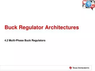
Buck Regulator Architectures. 4.3 Hysteretic Buck Regulators. Hysteretic Buck-Regulator Architecture. Ripple is needed to properly switch the comparator!. Simplest and fastest topology but variable frequency!. V. SW. V. Buck Switch stays on for an On-time Determined by V IN and R ON.

E N D
Buck Regulator Architectures 4.3 Hysteretic Buck Regulators
Hysteretic Buck-Regulator Architecture Ripple is needed to properly switch the comparator! Simplest and fastest topology but variable frequency!
V SW V Buck Switch stays on for an On-time Determined by VIN and RON IN t t SW Pin ON OFF -0.6V I L Inductor's current ripple determined by VIN, VOUT, On-time and L Inductor Current I OUT V OUT Output voltage ripple determined by inductor's and COUT ESR V (DC) Output Voltage OUT Reference Threshold Hysteretic Regulator Waveforms DI = DV Dt L
Calculating Switching Frequency • In most cases, switching frequency is determined by the output ripple voltage (ΔVOUT) resulting from the output capacitor’s ESR. The amplitude of ΔVOUT is described by the following two equations: • Combining these two equations yields an expression for the switching frequency. Note: If a speed up capacitor is used the circled term in the denominator of this equation becomes 1 which means the switching frequency value will increase.
LM3475/85 Using Electrolytic COUT • The graphic shows the output ripple and switch node voltage • The operating frequency is 1.43MHz • The feedback network does not use a CFF speed up capacitor
LM3475/85 Using Ceramic COUT • An example of using a ceramic output capacitor with almost no ESR • Operating frequency has dropped and can not be calculated using the equation mentioned previously • Reason: The output ripple is 90°phase shifted from the switching action
LM3475/85 – Working with Ceramic Capacitors • Desire • Use ceramic capacitors • Challenge • Ceramic capacitors have very low ESR • Results in 90°phase shift of output voltage ripple, resulting in low operating frequency and increased output ripple • Solution • Add a low value resistor in series with the ceramic output capacitor to provide an ESR value • Although counter intuitive, this combination provides highly accurate control over output voltage ripple
Working with Ceramic Capacitors Another Technique By adding the three components circled in the diagram, we provide AC feedback in phase with the switching action. The 100pF capacitor provides bypassing of any high frequency edge noise which may cause improper triggering of the FB comparator. This method has a number of advantages.