Download
1 / 21
210 likes | 246 Views
MERLIN BEAMLINE ARPES refocusing mirror system. F. Gicquel 03-07-08. The MERLIN beamline 4-0-3. The endstations area. Mirrors to be reviewed. The mirror system. View from an inboard downstream position. View from an outboard upstream position. The mirrors on the mounting plate.

E N D
MERLIN BEAMLINEARPES refocusing mirror system F. Gicquel 03-07-08
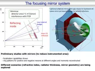
The MERLIN beamline 4-0-3 4-0-3 ARPES KB mirror review
The endstations area Mirrors to be reviewed 4-0-3 ARPES KB mirror review
The mirror system View from an inboard downstream position View from an outboard upstream position 4-0-3 ARPES KB mirror review
The mirrors on the mounting plate M333 Silicon sagittal cylinder M332 17-4PH bender 4-0-3 ARPES KB mirror review
The stand The 4 posts are ASTM A500B rectangular tubing 8” x 6” x .25” Zanite filled Cross members are - 4” x 8” x .25” - 2” x 8” x .25” Floor plate 1” thick 49.5” 33.5” 36.25” 4-0-3 ARPES KB mirror review
Stability of the stand With grout first mode at 69Hz Without grout first mode at 49Hz Engineering note number M7629 written by Will Thur recommends to have the first mode above 20Hz only considering the presence of a cryocompressor nearby I use 60Hz as my lower limit. Therefore I recommend grouting the stand. 4-0-3 ARPES KB mirror review
Earthquake safety • Total mass: 2337lb • Pull out load per anchor : F=(2337*.7*(33.971/32))/2 =868.5 lbs • Shear load : F=2337*.7/4=409 lbs => The 1/2” HDI expansion shell is suitable (2380 lbs capacity in pull out, 1780 lbs in shear) Results pending survey of floor for existing shells 4-0-3 ARPES KB mirror review
Strut structure Vertical struts centered on bender main axis for easy adjustment Most of the adjustment can be done from the aisle side 4-0-3 ARPES KB mirror review
Vacuum vessel ports Downstream diagnostic Coupling mechanisms Upstream diagnostic Diagnostic port Diagnostic port Upper part of the linkage with actuators 4-0-3 ARPES KB mirror review
View ports for coated surfaces mask Downstream Bender clamp Upstream Bender clamp 4-0-3 ARPES KB mirror review
M332: description and specifications 4-0-3 ARPES KB mirror review
FEA from vacuum load 4-0-3 ARPES KB mirror review
Total deformation under vacuum 4-0-3 ARPES KB mirror review
Bender anchor points displacement vacuum load modifies the adjustment of the benders by 1.13mm or about 1 part in 10,000 4-0-3 ARPES KB mirror review
Bender coupling 4-0-3 ARPES KB mirror review
Clamp details Recess to register vertical spring and its clamp Contacts on 2 lands on both sides allows to apply torque with minimum constrain Relief for mirror edge Recess to register leaf spring and its clamps 4-0-3 ARPES KB mirror review
Linkage Clamp nut (2x) Washer (2x) Precision ball (2x) Threaded rod Bracket bolted to actuator 4-0-3 ARPES KB mirror review
Sagittal mirror 4-0-3 ARPES KB mirror review
Kinematic support Spring plunger Locking screw Adjusting set screw Spherical contact In green: supportsIn red: spring plungers 4-0-3 ARPES KB mirror review
Sagittal anchor points displacement 4-0-3 ARPES KB mirror review