Download
1 / 48
520 likes | 1.07k Views
Chapter 5 Basic Processing Unit. Processing Unit. A processor is the responsible for reading program instructions from the computer’s memory and executing them. It fetches one instruction at a time. It decodes (interprets) the instruction. Then, it carries out the actions specified.

E N D
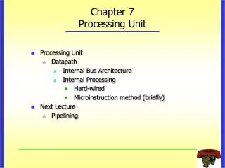
Processing Unit • A processor is the responsible for reading program instructions from the computer’s memory and executing them. • It fetches one instruction at a time. • It decodes (interprets) the instruction. • Then, it carries out the actions specified.
Processor’s building blocks • PC provides instruction address. • Instruction is fetched into IR • Instruction address generator updates PC • Control circuitry interpret instruction and generate control signals to perform the actions needed.
A digital processing system Contents of register A are processed and deposited in register B.
Why multi-stage? • Processing moves from one stage to the next in each clock cycle. • Such a multi-stage system is known as a pipeline. • High-performance processors have a pipelined organization. • Pipelining enables the execution of successive instructions to be overlapped. • Pipelining will be discussed later.
Instruction execution • Pipelined organization is most effective if all instructions can be executed in the same number of steps. • Each step is carried out in a separate hardware stage. • Processor design will be illustrated using five hardware stages. • How can instruction execution be divided into five steps?
A memory access instruction: Load R5, X(R7) • Fetch the instruction and increment the program counter. • Decode the instruction and read the contents of register R7 in the register file. • Compute the effective address. • Read the memory source operand. • Load the operand into the destination register, R5.
A computational instruction: Add R3, R4, R5 • Fetch the instruction and increment the program counter. • Decode the instruction and read registers R4 and R5. • Compute the sum [R4] [R5]. • No action. • Load the result into the destination register, R3. • Stage 4 (memory access) is not involved in this instruction.
Summary – Actions to implement an instruction • Fetch an instruction and increment the program counter. • Decode the instruction and read registers from the register file. • Perform an ALU operation. • Read or write memory data if the instruction involves a memory operand. • Write the result into the destination register. • This sequence determines the hardware stages needed.
Hardware components: Register file • A 2-port register file is needed to read the two source registers at the same time. • It may be implemented using a 2-port memory.
Alternative implementation of 2-port register file • Using two single-ported memory blocks.
A conceptual view – computational instructions • Both source operands and the destination location are in the register file. [RB] [RC] [RA]
A conceptual view – immediate instructions • One of the source operands is the immediate value in the IR. [RC] [RA]
A 5-stage implementation of a RISC processor • Instruction processing moves from each stage to the next in every clock cycle. • The instruction is decoded and the source registers are read in stage 2. • Computation takes place in the ALU in stage 3.
A 5-stage implementation of a RISC processor • If a memory operation is involved, it takes place in stage 4. • The result of the instruction is stored in the destination register in stage 5.
The datapath – Stages 2 to 5 • Register file Inter-stage registers needed to carry data from one stage to the next. • ALU stage • Memory stage • Back to the register file
Register file – Stages 2 & 5 • Address inputs connected to corresponding fields in IR. • Source registers are read and their contents stored in RA and RB. • The result of the instruction is stored in the destination register selected by address C.
ALU stage • ALU performs calculation specified by the instruction. • Multiplexer MuxB selects either RB or the Immediate field of IR. • Results stored in RZ. • Data to be written in the memory are transferred from RB to RM.
Memory stage • For a memory instruction, RZ provides memory address, and MuxY selects data read to be placed in RY. • RM provides data for a memory write operation. • For a calculation instruction, MuxY selects [RZ] to be placed in RY. • Input 2 of MuxY is used in subroutine calls.
Memory address generation • MuxA selects the PC when fetching instructions. • The Instruction address generator increments the PC after fetching an instruction. • It also generates branch and subroutine addresses. • MuxA selects RZ when reading or writing data operands.
Processor control section • When an instruction is read, it is placed in IR. • The control circuitry decodes the instruction. • It generates the control signals that drive all units. • The Immediate block extends the immediate operand to 32 bits as specified in the instruction.
Instruction address generator • Connections to RY and RA are used for subroutine call and return.
Example: Add R3, R4, R5 • Memory address [PC], Read memory, IR Memory data, PC [PC] 4 • Decode instruction,RA [R4], RB [R5] • RZ [RA] [RB] • RY [RZ] • R3 [RY]
Example: Load R5, X(R7) • Memory address [PC],Read memory, IR Memory data, PC [PC] 4 • Decode instruction, RA [R7] • RZ [RA] Immediate value X • Memory address [RZ], Read memory, RY Memory data • R5 [RY]
Example: Store R6, X(R8) • Memory address [PC], Read memory, IR Memory data, PC [PC] 4 • Decode instruction, RA [R8], RB [R6] • RZ [RA] Immediate value X, RM [RB] • Memory address [RZ], Memory data [RM], Write memory • No action
Unconditional branch • Memory address [PC], Read memory, IR Memory data, PC [PC] 4 • Decode instruction • PC [PC] Branch offset • No action • No action
Conditional branch: Branch_if_[R5]=[R6] LOOP • Memory address [PC], Read memory, IR Memory data, PC [PC] 4 • Decode instruction, RA [R5], RB [R6] • Compare [RA] to [RB], If [RA] = [RB], then PC [PC] Branch offset • No action • No action
Subroutine call with indirection: Call_register R9 • Memory address [PC], Read memory, IR Memory data, PC [PC] 4 • Decode instruction, RA [R9] • PC-Temp [PC], PC [RA] • RY [PC-Temp] • Register LINK [RY]
Control signals • Control multiplexer selection to guide the flow of data. • Set the function performed by the ALU. • Determine when data are written into the PC, the IR, the register file and the memory. • Intermediate registers are always enabled.
Memory access • Cache memory described earlier as faster and smaller storage that is an adjunct to the larger and slower main memory. • When data are found in the cache, access to memory can be completed in one clock cycle. • Otherwise, read and write operations may require several clock cycles to load data from main memory into the cache. • A control signal is needed to indicate that memory function has been completed (MFC). E.g., for step 1: • Memory address [PC], Read memory, Wait for MFC,IR Memory data, PC [PC] 4
Control signal generation • Actions to fetch & execute instructions have been described. • The necessary control signals have also been described. • Circuitry must be implemented to generate control signals so actions take place in correct sequence and at correct time. • There are two basic approaches: hardwired control and microprogramming • Hardwired control involves implementing circuitry thatconsiders step counter, IR, ALU result, and external inputs. • Step counter keeps track of execution progress,one clock cycle for each of the five steps described earlier.
CISC processors • CISC-style processors have more complex instructions. • The full collection of instructions cannot all be implemented in a fixed number of steps. • Execution steps for different instructions do not all followa prescribed sequence of actions. • Hardware organization should therefore enablea flexible flow of data and actions to accommodate CISC.
Bus • An example of an interconnection network. • When functional units are connected to a common bus, tri-state drivers are needed.
Example: Add R5, R6 • Memory address [PC], Read memory, Wait for MFC, IR Memory data, PC [PC] 4 • Decode instruction • R5 [R5] [R6]
Example: And X(R7), R9 • Memory address [PC], Read memory, Wait for MFC, IR Memory data, PC [PC] 4 • Decode instruction • Memory address [PC], Read memory, Wait for MFC, Temp1 Memory data, PC [PC] 4 • Temp2 [Temp1] [R7] • Memory address [Temp2], Read memory, Wait for MFC, Temp1 Memory data • Temp1 [Temp1] AND [R9] • Memory address [Temp2], Memory data [Temp1], Write memory, Wait for MFC
Microprogramming • Microprogramming is a software-based approach tothe generation of control signals. • The values of the control signals for each clock period are stored in a microinstruction (control word). • A processor instruction is implemented by a sequence of microinstructions that are placed in a control store. • From decoding of an instruction in IR, the control circuitry executes the corresponding sequence of microinstructions. • PC maintains the location of the current microinstruction.
Microprogramming • Microprogramming provides the flexibility neededto implement more complex instructions in CISC processors. • However, reading and executing microinstructions incurs undesirably long delays in high-performance processors.