Download
1 / 54
550 likes | 815 Views
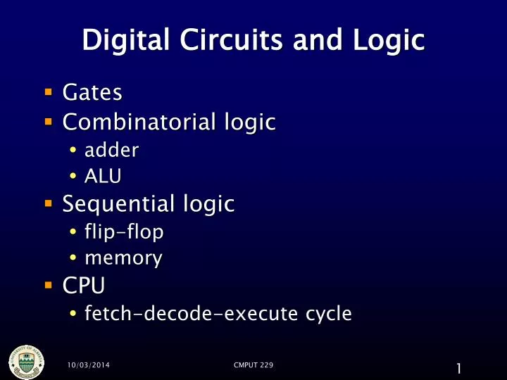
Digital Circuits and Logic. Gates Combinatorial logic adder ALU Sequential logic flip-flop memory CPU fetch-decode-execute cycle. How to make a computer. Computers are electronic equipment contain many connected electronic components memory Central Processing Unit ( CPU )

E N D
Digital Circuits and Logic • Gates • Combinatorial logic • adder • ALU • Sequential logic • flip-flop • memory • CPU • fetch-decode-execute cycle CMPUT 229
How to make a computer • Computers are electronic equipment • contain many connected electronic components • memory • Central Processing Unit (CPU) • specialized devices (network, video, etc.) • components largely made of circuits containing wires and gates CMPUT 229
Logic Level • A Boolean logical signal always takes one of two logic levels. • on / off • high (H) / low (L) • one (1) / zero (0) • true (T) / false (F) • positive / negative • Why two levels ? • Why not use, say, 4 levels? • For example, electrical voltage as • 0 v, 5v, 10v, and 20v CMPUT 229
Gates • Tiny electronic switches • made of transistors • implement Boolean logic • 0/1 low/high voltage • digital • for given inputs, produce known output • according to truth table • represented in circuit diagrams by symbols CMPUT 229
Gates NOT In Out 0 1 1 0 CMPUT 229
AND In 1 In 2 Out 0 0 0 0 1 0 1 0 0 1 1 1 Gates CMPUT 229
Gates NAND In 1 In 2 Out 0 0 1 0 1 1 1 0 1 1 1 0 CMPUT 229
In 1 In 2 Out 0 0 0 0 1 1 1 0 1 1 1 1 Gates OR CMPUT 229
XOR In 1 In 2 Out 0 0 0 0 1 1 1 0 1 1 1 0 Gates CMPUT 229
Implementation of Logic Gates • The NAND gate, the basic logic gate • easier to manufacture • any other logic gate can be made from a combination of NAND gates CMPUT 229
Implementation of Logic Gates • CMOS • The standard, 4000 series (4011) CMPUT 229
Implementation of Logic Gates • TTL • The 4011's TTL counterpart is the 7400 CMPUT 229
Logic Circuits • Combinatorial Logic • Output depends solely on the input values • Example: • arithmetic logic unit (ALU) • Sequential logic • output depends on • the present input, and • the history of the input • Examle: • Flip-flop, Memory CMPUT 229
Combinatorial logic • What about more complex truth tables? • Made by combining many gates together • wires connect inputs and outputs • each wire can carry only one bit, 0 or 1 CMPUT 229
Combinatorial logic • Circuits made from collections of gates • outputs depend only on inputs • not on prior state • characterized by truth table • comparable to Boolean expression CMPUT 229
0 A 1 B X 1 C Combinatorial logic boolean expression X = (A & ~B) | (B & C) truth table logic circuit 0 0 0 0 1 1 1 1 1 all three of forms are equivalent; each can be converted to the other two. CMPUT 229
DeMorgan’s Law CMPUT 229
In 1 In 2 Out 0 0 0 0 1 1 1 0 1 1 1 1 CMPUT 229
Combinatorial logic • Many parts of a computer are constructed of combinatorial logic • adder circuit • performs addition • arithmetic logic unit (ALU) • performs many kinds of arithmetic and bitwise logical operations • contains adder circuit • multiplexer and decoder • direct bit traffic between components CMPUT 229
Adder • A combinatorial circuit that adds binary values • according to this truth table Carry is equivalent to AND Sum is equivalent to XOR CMPUT 229
Adder Carry In 1 In 2 Sum This circuit can add two binary digits and is called a half-adder CMPUT 229
1 5 3 + 4 3 8 Adder Why “half-adder”. . . ? 1 9 1 . . . because to add multi-digit numbers each column requires two additions CMPUT 229
half adders Full adder in 1 This circuit is called a full adder and can add three binary digits in 2 carry out carry in This OR gate combines the carries from the two half-adders sum CMPUT 229
Ripple-carry adder A3 A2 A1 A0 B3 B2 B1 B0 out3 out2 out1 out0 CMPUT 229
0 1 0 1 0 1 1 0 Ripple-carry adder A3 A2 A1 A0 0101 + 0110 = 1011 B3 B2 B1 B0 0 1 0 0 0 0 1 0 1 0 0 0 0 1 0 1 1 out3 out2 out1 out0 CMPUT 229
Ripple-carry adder • So named because gate results (including carries) propagate (“ripple”) from LSB to MSB • right to left • corresponds to how humans add numbers with pen and paper • More sophisticated, faster, adder circuits exist that can create the higher order carries more quickly CMPUT 229
Adder A3-A0 B3-B0 Adders (and other arithmetic circuits) are usually drawn like this in block diagrams inputs + output collections of parallel, related wires like this are known as buses; they carry multi-bit values between components out3-out0 CMPUT 229
Arithmetic • Computers need to do more than just addition • arithmetic: + – * / % • logic: & | ~ << >> • Need a circuit that can select operation to perform CMPUT 229
Multiplexer (Mux) B A A B S S C C CMPUT 229
Arithmetic Logic Unit (ALU) A B more operations here . . . op 0 op 1 op 2 op 3 + * & << Multiplexer: a combinatorial circuit which selects exactly one input 0 1 2 3 .. MUX op op selects operation: 0 = add, 1 = multiply, ... out CMPUT 229
Arithmetic Logic Unit (ALU) A = 15 B = 2 for example: compute 15 << 2 more operations here . . . op 0 op 1 op 2 op 3 + * & << other results also computed but ignored by multiplexer 0 1 2 3 .. MUX op = 3 out = 60 CMPUT 229
How to design a logic circuit for a given truth table? • For each row in the truth table whose output value is 1, construct a logic expression of the conjunction of all input column values • Form the disjunction of all conjunctive formulas obtained in step 1 • Simplify the disjunction obtained from Step 2 • Construct the logic circuit from the simplified logical expression in Step 3 CMPUT 229
Memory • Computers need memory for storage • Different kinds of memory distinguished by speed, size, cost and proximity to CPU • main memory • slowish, huge, cheap, far from CPU • typical size 109 bits • cache • fast, medium-sized, expensive, near to CPU • typical size 106 bits • registers • extremely fast, tiny, very expensive, located on CPU • in MIPS (32 GPRs)×32 bits = 1024 bits CMPUT 229
Memory • The smallest piece of memory is a single binary digit (bit) • can hold 0 or 1 only • A one-bit memory is called a flip-flop or a data latch • because its value can flip and flop between 0 and 1 • because it can latch onto a data value and store it CMPUT 229
Flip-flop • Flip-flop needs two operation modes • write: store (memorize) a value • read: load (recall) a previously stored value • Also need • data in • for telling flip-flop what value to store (0 or 1) • used only when writing • data out • for finding out what value flip-flop currently contains (0 or 1) • used only when reading CMPUT 229
Flip-flop • Flip-flop can be implemented with gates • Not combinatorial logic • because current output may depend on previous state • Example of sequential logic • current output depends on inputs and prior output CMPUT 229
Flip-flop NOR gate: OR gate followed by NOT gate data in data out read/write read/write control: 0 = read, 1 = write CMPUT 229
Flip-flop: writing Try changing data in to 0 and watch data out data in = 1 1 1 0 1 1 0 1 0 1 0 data out = 1 1 when read/write = 1, data out = data in read/write = 1 (write) CMPUT 229
when read/write = 0, no signals in box can change, data out holds value regardless of data in Flip-flop: reading data in = ? ? 0 0 0 1 0 ? ? 1 0 data out = 1 0 read/write = 0 (read) CMPUT 229
Flip-flop D = data in Q = data out Flip-flops are often drawn like this in block diagrams D Q CK CK is read/write (“clock” because this input is often connected to computer’s processor clock) CMPUT 229
Flip-flop using NAND Gates CMPUT 229
Flip-flop using NAND Gates Data In Data Out read/write CMPUT 229
Memory • Memory can store many bits independently • many flip-flops • Need to identify which bit (flip-flop) to read or write • Give each flip-flop a unique number (address) CMPUT 229
Memory Decoder: feeds input to selected output, 0 to all others data in D Q address 0 CK D Q data out 0 0 address 1 rd/wr 1 1 CK DEC MUX 2 2 3 3 D Q ... ... address 2 CK D Q address address 3 CK . . . millions more flip-flops . . . CMPUT 229
Memory: writing Writing value 1 to flip-flop at address 2 data in ? D Q 1 address 0 0 CK ? D Q data out 0 0 address 1 rd/wr 0 1 1 CK DEC MUX 2 2 1 1 3 3 D Q 1 ... ... address 2 1 CK ? D Q address address 3 0 CK 2 . . . millions more flip-flops . . . CMPUT 229
Memory: reading Reading value from flip-flop at address 2 data in D Q address 0 0 CK D Q data out 0 0 address 1 rd/wr 0 1 1 CK DEC MUX 2 2 0 1 1 3 3 D Q 1 ... ... address 2 0 CK D Q address address 3 0 CK 2 . . . millions more flip-flops . . . CMPUT 229
Memory • Memory usually operates in terms of bytes (8 bits), not single bits • Repeat memory circuit eight times • connect each memory circuit to one of the eight lanes of the data bus • reads and writes occur in parallel for each bit in byte CMPUT 229
Central Processing Unit (CPU) • Coordinates all computer’s components according to program being run • Contains • registers • ALU • program counter (PC) • address of current instruction • instruction register (IR) • copy of current instruction • control logic • Runs programs using fetch-(decode)-execute cycle CMPUT 229
CPU IR Registers out Memory in Control logic rd/wr addr ALU PC CMPUT 229