Download
1 / 83
930 likes | 1.5k Views
ROTATING BIOLOGICAL CONTACTOR (RBC) PROCESS. Prepared By Michigan Department of Environmental Quality Operator Training and Certification Unit. ROTATING BIOLOGICAL CONTACTORS. Contactors. Primary Treatment. Secondary Clarifier. Effluent. Influent. Solids Removal.

E N D
ROTATING BIOLOGICAL CONTACTOR (RBC) PROCESS Prepared By Michigan Department of Environmental Quality Operator Training and Certification Unit
ROTATING BIOLOGICAL CONTACTORS Contactors Primary Treatment Secondary Clarifier Effluent Influent Solids Removal
RBC Secondary Treatment Rotating Plastic Media Provides Large Surface Area 1.6 rpm 40 % Submerged Microorganisms “Treat” the Wastewater by Using Organics
New Cells NH3 CO2 H2O Wastewater Slime Layer Cell Membrane Food Storage Oxygen Enzymes (Absorption) Adsorbed Particle Soluble Organics
Oxygen Organics Liquid Film Biomass Media (disc) Oxygen
Liquid Film Liquid Film Random Continuous Sloughing OXYGEN Organics BIOMASS Media
RBC Flow Scheme INFLUENT Primary Treatment Rotating Biological Contactors Pretreatment Disinfection Secondary Clarifiers EFFLUENT Solids Handling
ADVANTAGES OF RBC PROCESS Simple Operation Low Energy Requirements Nitrification Few Nuisances Wide Flow Range Large Biological Population
ADVANTAGES OF RBC PROCESS Simple Operation Low Energy Requirements Nitrification Few Nuisances Wide Flow Range Large Biological Population Handles Shock Loads Low Head Loss
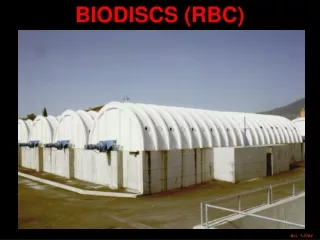
DISADVANTAGES OF RBC PROCESS Limited Controls Enclosures Limited Experience and Training
RBC COMPONENTS CONTACTOR TANK CLARIFIER
RBC COMPONENTS CONTACTOR Discs Shaft Individual Disc
Media “High Density” Polyethylene Carbon Black
Media – Irregular Surface Maintain Spacing Increases Rigidity Increases Surface Area Increases Contact Time
Media – Irregular Surface “Corrugated”
Media – Irregular Surface “Dimpled”
Media 1 Inch BIOMASS
10 to 12 Ft Diameter ~ 25 Ft Long
Media High Density Standard Density 1 inch ¾ inch
Shaft Square Shaft
Bearings “Floating” Self-aligning
Shaft Bearing Load Cell Coupling for Hydraulic Pump Load Cells
Load Cells Purpose: Determine Weight of Contactor to Determine Amount (Thickness) of Biomass
Drive Systems - Chain
Drive Systems - Direct
Drive Systems - Air Air Cups Air Header Air Diffusers
Drive Systems - Air Air Cups Rotation Air Header
Drive Systems - Air
Drive Systems - Air
Drive Systems - Combination
Containment Just Large Enough Good Contact Minimal Short Circuiting Good Mixing
“Train” FLOW FLOW RBC Systems Usually More Than One Contactor with Flow Progressing in Series in a “Train”
Flow Schemes Parallel to Shaft Direction of Flow Perpendicular to Shaft Contactors May be Arranged With Flow Either Parallel or Perpendicular to Shafts
Influent Effluent Baffles “Train” Small Systems – Train May be One Contactor with Separations and Baffles
Larger Systems – Contactors are Set in Series in Separate Tanks or in One Tank With Enclosure Effluent Influent Baffles
Train Baffles FLOW FLOW Baffles Separate Each Contactor, Dividing the Flow in the Train Into Separate Complete Mix Zones of Treatment
Train Baffles FLOW Each Zone of Treatment is Called a “Stage”
Train Baffles FLOW 5 Stages (Zones of Treatment)


![ERYTHROCYTES [RBCs]](https://cdn3.slideserve.com/6499114/erythrocytes-rbcs-dt.jpg)