Download
1 / 31
320 likes | 398 Views
Learn about AC circuits, phasor diagrams, resistance, reactance, resonant circuits, power factor, and practical applications in speaker systems. Includes worked examples and comparison of capacitors and inductors.

E N D
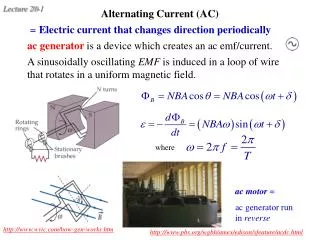
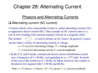
28.1. Alternating Current Reminder: All waves can be analyzed in terms of sinusoidal waves (Fourier analysis Chap 14). Sinusoidal wave (Chap 13) : Vp sin Angular frequency : [] = rad/s = / 6 = phase
Example 28.1. Characterizing Household Voltage Standard household wiring supplies 110 V rms at 60 Hz. Express this mathematically, assuming the voltage is rising through 0 at t = 0.
28.2. Current Elements in AC Circuits • Resistors • Capacitors • Inductors • Phasor Diagrams • Capacitors & Inductors: A Comparison
Displacing Functions g g is moved to the right (forward) by to give f. f x x cos Displacement: sin is cos moved forward by /2. Phase: sin lags cos by /2. sin Derivative: moves sinusoidal functions backward by /2. phase is increased by /2. Integral: moves sinusoidal functions forward by /2. phase is decreased by /2.
Resistors I + VR + I & V in phase
Capacitors When V(t) > 0 : I + + VC I leads V by 90 I peaks ¼ cycle before V Capacitive reactance DC: open ckt. HF: short ckt.
Inductors When V(t) > 0 : I L + + I trails V by 90 I peaks ¼ cycle after V Inductive reactance DC: short ckt. HF: open ckt.
Table 28.1. Amplitude & Phase in Circuit Elements Resistor V & I in phase Capacitor V lags I 90 V leads I 90 Inductor
Example 28.2. Equal Currents? • A capacitor is connected across a 60-Hz, 120-V rms power line, • and an rms current of 200 mA flows. • Find the capacitance. • What inductance, connected across the same powerline, • would result in the same current? • (c) How would the phases of the inductor & capacitor currents compare? (a) (b) Capacitor: ICleads V by 90. Inductor: V leads ILby 90. (c) ICleads ILby 180.
Phasor Diagrams Phasor = Arrow (vector) in complex plane. Length = mag. Angle = phase. V leads I by 0. ( same phase ) V leads I by 90. V leads I by 90. ( V lags I by 90 )
Capacitors Revisited I + VC Vp e i t I leads V by 90 Taking the real part as physical Taking the imaginary part as physical Impedance
Inductors Revisited I L + Vp e i t I lags V by 90 Taking the real part as physical Taking the imaginary part as physical
Capacitors & Inductors: A Comparison C L translator: E B q B V I Z Y
Table 28.2. Capacitors & Inductors Defining relation Defining relation;differential form Opposes change in V I Energy storage Open circuit Short circuit Behavior in low freq limit Short circuit Open circuit Behavior in high freq limit Reactance Admittance / Impedance V leads by 90 Phase I leads by 90
Application: Loudspeaker Systems Loudspeaker C passes High freq Loudspeaker system with high & low frequency filters. L passes low freq
28.3. LC Circuits I V +
Analyzing the LC Circuit I V +
Resistance in LC Circuits – Damping + VR I L + VC + (see next page)
Resistance in LC Circuits – Damping + VR I VC + L + (see next page)
Solutions to Damped Oscillator Ansatz:
28.4. Driven RLC Circuits & Resonance + VR I + L + VC + Driven damped oscillator : Long time: oscillates with frequency d. Resonance if d =0.
Resonance in the RLC Circuit VC& VL are 180 out of phase. i.e., if
Frequency Response of the RLC Circuit Series circuit same I phasor for all. VR in phase with I. VC lags I by 90. VL leads I by 90. High Q Low Q See Prob 71 for definition of Q. At resonance, = 0.
Example 28.4. Designing a Loud Speaker System • Current flows to the midrange speaker in a loudspeaker system through a 2.2-mH inductor in series with a capacitor. • What should the capacitance be so that a given voltage produces the greatest current at 1 kHz ? • If the same voltage produces half this current at 618 Hz, • what is the speaker’s resistance ? • If the peak output voltage of the amplifier is 20 V, • what will be the peak capacitor voltage be at 1 kHz ? (a) Greatest I is at resonance:
(b) If the same voltage produces half this current at 618 Hz, what is the speaker’s resistance ? At resonance: • If the peak output voltage of the amplifier is 20 V, • what will be the peak capacitor voltage be at 1 kHz ? Peak voltage is at resonance (1 kHz).
28.5. Power in AC Circuits Capacitor: I leads V by 90 , P = 0 Resistor: I & V in phase , P > 0 I & V out of phase , P Power factor Dissipative power = I2 R large power factor reduces I & hence heat loss.
Conceptual Example 28.1. Managing Power Factor You’re chief engineer of a power company. Should you strive for a high or a low power factor on your lines? Power factor Generator : fixed Vrms . To maintain fixed <P>, Irms cos = const. Smaller power factor higher Irms. higher power loss. Ans.: keep power factor close to 1.
Making the Connection Transmission losses on a well-managed electric grid average about 8% of the total power delivered. How does this figure change if the power factor drops from 1 to 0.71? To deliver the same power Transmission losses: ( doubles to 16% )
28.6. Transformers & Power Supplies Transformer: pair of coils wound on the same (iron) core. Works only for AC.
Direct-Current Power Supplies Diode passes + half of each cycle Diode Diode cuts off half of each cycle RC (low freq) filter