Download
1 / 39
410 likes | 551 Views
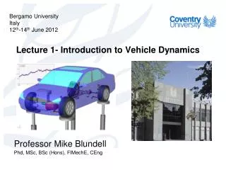
Bergamo Univeristy Italy June 12 th -13 th 2012. Lecture 3 – Use of CAE and ADAMS. Professor Mike Blundell Phd, MSc, BSc (Hons), FIMechE, CEng. Concept. Design. Validate. Assembly. Service. IMPROVEMENT. Improvements with MBS. With MBS. RISK. INFORMATION.

E N D
Bergamo Univeristy Italy June 12th-13th 2012 Lecture 3 – Use of CAE and ADAMS Professor Mike Blundell Phd, MSc, BSc (Hons), FIMechE, CEng
Concept Design Validate Assembly Service IMPROVEMENT Improvements with MBS With MBS RISK INFORMATION Product Development Process for Manufacturers
CAD FEA CFD ? Controls Hydraulics Testing Integrated CAE Technologies MBS
Multibody Systems Analysis (MBS) Virtual Prototyping (MBS) may be summarised as: • The Analysis and Simulation of Mechanical Systems • Systems can consist of rigid and flexible bodies • Bodies are assembled using rigid joints or flexible connections • System elements such as springs and bushes can be nonlinear • The mechanism can move through large displacement motion • Automatic formation and solution of equations of motion • Animated and plotted presentation of results • Commercial Software available – ADAMS, SIMPACK, DADS, …
Spherical Cylindrical Revolute Translational Planar Fixed Universal Rack & Pinion Typical Constraint Elements - Joints
Joint Library Cylindrical Joint Spherical Joint
Joint Library Planar Joint Revolute Joint
Joint Library Translational Joint Universal Joint
Main Types of Analysis • KINEMATIC - Movement controlled by joint selection and motion inputs.Movements not effected by external forces or mass properties.Systems have zero rigid body Degrees of Freedom. • STATIC - Determine static equilibrium position and reaction forces. Velocities and accelerations are set to zero. Often needed before dynamic analysis (ie. full vehicle models). Can be run QUASI-STATIC in time domain. • DYNAMIC - Complete nonlinear transient multi-degree of freedom systems using numerical integration to solve the equations of motion. Users can select the integrator for solution and control the accuracy of the solution process.
MADYMO Simulation of Pedestrian Impact • Pedestrian Human Body Model positioned: - Walking posture - Knee extended - balanced in an upright position • No pedestrian initial velocity • Vehicle initial velocity 39 km/h • Bumper level 390 mm • Bumper lead distance 200 mm • Hood edge level 720 mm
Adaptable Car Structures (ACS) Active-reversible bumper and bonnet concept (Pneumatic Muscle) Bonnet in active position
Characteristic Curves of Automotive Suspension • Toe, Caster, Camber curves are essential properties of a suspension • Curves represent change in angular orientation of wheel under different loading conditions • Curves must be continually evaluated as design changes
Typical Problem Statement • Packaging problems with current design • Tie-rod spindle connection point must be moved • Would like to move tie rod: • 10 mm outboard • 14 mm aft • 15 mm up
A Past Approach • Run two analyses: nominal and design change (considered) • Compare the results
Modern Methods • Setup Design of Experiments Analysis (DOE) • Define design space • Define trial runs
Application of DOE • Utilize parametric modeling tool • Analyse set of trials picked by DOE theory • Use DOE theory and the response surface method • Fitted results give continuous information throughout design space
Start with Design Space Parameter 2 Parameter 1
Add DOE Design Points Parameter 2 Parameter 1
Assign Trial Numbers 1 Parameter 2 2 4 3 5 7 6 8 Parameter 1 9
Analyze Model at Each Trial Trial Response Time
Calculate Objective at Each Trial Trial Response Time
Trial Response Time Map Trial Objectives back to Design Space
Create Response Surface Parameter 2 Objective Parameter 1
Provides continuous knowledge within design space! Can be extended (hard to visualize) More than 2 factors More complex objective types Response Surface Method
Forced Contact Step Output • Animate using defined output steps • Or animate additional contact frames • Displays contacts between output steps 50 STEPS 152 STEPS
ADAMS/Flex • Integrating System-Level Motion Simulation and Component-Level FEA FE Modes ADAMS Simulation Stress Distribution
Flexible Satellite with Automatic Controls • Stabilizing the satellite’s orientation during deployment of flexible solar panels
Digital Functional Vehicle Full Vehicle Test Rigs Road Driver Chassis Engine Driveline Body Suspension Valvetrain Transmission Body-in-white Steering Cranktrain Clutch Frame Brakes Chain/Belt Differential Seating Tires Acc. Drives Axles/CV Restraints
Tutorial 4 - ADAMS Demonstration Session • Using ADAMS/Solver Files (Solver) • Building Models interactively in ADAMS/VIEW • Using an ADAMS/Command Files (AVIEW)
10 01 04 08 BODY/GROUND 09 02 01 07 05 02 03 05 04 11 03 12 Z 06 09 X 06 Y Double Wishbone Example • Prepare a System Schematic • Calculate the model Degrees of Freedom • Plan the ADAMS/Solver Input File