Download
1 / 15
150 likes | 300 Views
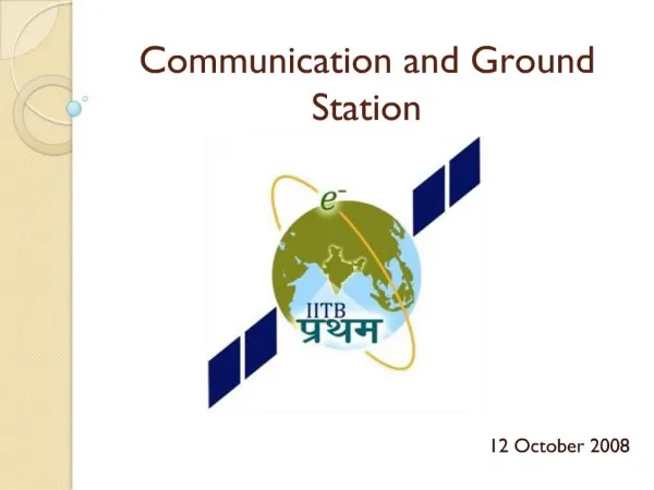
Ground Station Workshop A flashback. By: Deepika Thakur. Conceptual design of the Communication Subsystem . Why 437 MHz and 145 MHz. Availability of frequency bands Payload Requirements Availability of modules Interband Interference and noise Amateur frequency band. Why FSK?.

E N D
Ground Station Workshop A flashback By: DeepikaThakur
Why 437 MHz and 145 MHz • Availability of frequency bands • Payload Requirements • Availability of modules • Interband Interference and noise • Amateur frequency band
Why FSK? • Spectrally Efficient • Moderate value of Eb/No • Modules Readily Available • Low intersymbol interference as compared to FM
Why AX.25 protocol? • It is a standard protocol used by the amateur radio enthusiasts • It is robustly designed for packet data transfer
Why monopole? • Being Omnidirectional it reduces the constraints on attitude control • It produces a linearly polarized beam. • High polarization purity can be obtained by careful design of the antenna. • The length of the antenna is comparable to the satellite dimensions • It is easy to fabricate . • The loss in gain can be compensated by using a directional antenna on the ground station
Why beacon is separate from OBC? • Indicator of satellite is alive • Should work even if OBC fails • Hence, no dependency on OBC
Why CC 1020? • It is industrial grade. • It is operational over a frequency band of 405MHz to 470 MHz and is tunable. • It’s power requirements are low. • It supports packet data transmission. • Maximum bitrate is 156.2 kBps which is much higher than our requirements. • space heritage.
Why ADF? • It is industrial grade. • It is operational over a frequency band of 128MHz to 150 MHz and is tunable. • It’s power requirements are low. • Maximum bitrate is 100 kBps which is much higher than our requirements. • It has Space heritage.
Why crossed yagi? • The onboard monopoles are transmitting linearly polarised light for satisfying payload requirements. • The signal strength of the incoming wave at the Groundstation needs to be determined in 2 perpendicular planes to get the angle of polarisation • The difference in polarisation angles is used for computation of TEC.
Why 4 antennae on GS? • The Groundstation at IITB serves the dual purpose of demodulation and Payload • The antennae to be used for demodulation cannot be used for measurement of polarization because of synchronization issues. • 2 antennae are needed at each frequency ; one for demodulation and one for polarisation measurement
How many LNA’s and why? • The polarisationmeaurement IC needs a signal strength level of -60 dBm. • The received Signal strength from link budget calculations is -110 dBm. • Hence we would require atleast 3 LNA’s for polarisation measurement • We would require atleast 1 LNA for CC1020 and ADF7020 to raise the strength of the incoming signal above the sensitivity levels
Why tracking above 300 elevation? • The free space losses during transmission is given by Friis formula: 22 + log (S/λ) • The slant range (S) increases with decreasing elevation angles increasing the free space losses • The attenuation also increases due to obstruction in the line of sight caused by Buildings, towers etc.
Yagi design and 4NEC2X • A yagi antenna consists of the following elements a) Director b) Reflector c) Folded dipole or feed element • The impedance of the Yagi should be matched to 50 ohms for it to transmit effectively • This is achieved using a balun of length λ/4. • The antenna is simulated and optimised using the 4NEC2 software