Download
1 / 20
200 likes | 319 Views
Aerogels. Invented by S. S. Kistler (Stanford U.) in 1931 lengthy process, first major breakthrough: supercritical drying of wet gels retaining volume of the gel “Forgotten” for almost 30 years “Re-invented” in the 1960’s in France second major breakthrough: sol-gel process

E N D
Aerogels • Invented by • S. S. Kistler (Stanford U.) in 1931 • lengthy process, • first major breakthrough: supercritical drying of wet gels • retaining volume of the gel • “Forgotten” for almost 30 years • “Re-invented” in the 1960’s in France • second major breakthrough: • sol-gel process • cutting Kistler’s method from weeks to hours JPL Website, Stardust Program • Very lightweight glass-like materials, but extremely fragile • At best: • 1.5 mg/cc, Guinness World Records • 99.8% porosity • 1000 times less dense than glass • about 40 times better thermal insulators than the best fiberglass
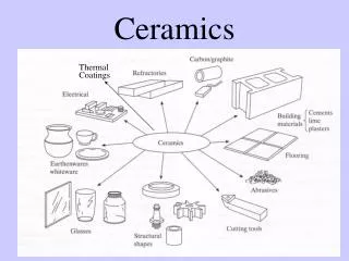
Current and Projected Use for Aerogels • Aerogels have been consideredfor: • thermal insulation (architectural, automotive industrial • applications); • acoustic insulation (buildings, automobiles, aircraft); • dielectrics (for fast electronics); • - supports for catalysts; and, • hosts of functional guests for chemical, • electronic and optical applications. • Silica aerogels have been actually used: • - as Cerenkov radiation detectors • aboard spacecraft: • as collectors of cosmic particles • (Stardust Program) • o for thermal insulation • (e.g., Sojourner Rover - 1997) • Commercialization has been slow, because silica aerogels are: • - fragile; • - hygroscopic; and, • - require supercritical fluid (SCF) extraction
Crosslinkingaerogels— Microscopically, nanocast conformal polymer coating on the silica nanoparticles thicker necks increase strength of material conformal polymer coating Micropores are blocked Leventis, et al, Nano Letters, 2002
Compressive Stress-Strain Curves for TemplatedAerogels Specific Energy Absorption (X-aerogel): 197 J/g in compression. Spider Dragline Silk: 165 J/g in tension.
Pontential Applications for CrosslinkedAerogels • Lightweight thermal insulation • Acoustic Insulation • Catalytic reformers and converters • Dielectrics • Ballistic materials • Filtration membranes • Membranes for fuel cells • Optical sensors • Aircraft structural components conformal polymer coating Leventis (2007), Luo, Lu and Leventis (2003) Cross-linked silica aerogel
Simulation of Two-spheres Model for Two Secondary Particles Connected to Each Other Secondary particles Polymer coating Section of Cross-linked Native Cross-linked Bending stresses at necks responsible for low failure strain leading to fragility in native silica aerogels Increase in the cross-linked aerogel stiffness with the amount of polymer addition Bending stress contours from FEM
SEM of CrosslinkedTemplatedAerogels (X-MP4-T045)
Nano-Computed Tomography (nano-CT) Optical Lens* Thin Single Crystal Scintillator f CCD Sample CCD Incident X-ray Beam Transmitted X-ray Image Light Light X-rays X-rays * Low depth of field, reject scattered light photons.
Crosslinked Silica Aerogel – MPM Simulation 3D discretized MPM simulation model 110 pixels along the length nano-CT structure for X-MP4-T045 Pixel size =480 nm/voxel; Average pore size 6−7μm
Crosslinked Silica Aerogel – MPM Simulation Flexural Modulus Estimation Weight ratio( Polymer: Silica)=70%: 30% Density of polymer = 1.2 g/cc Density of silica = 2.6 g/cc Modulus of polymer = 2 Gpa Modulus of silica =70 Gpa The volume ratio( Polymer: Silica) ≈5:1 The dimensionless radius of the model R=6 Based on the bending equation for the composite material The silica-aerogel modulus is about 3.889 Gpa
Simulation Results • Microstructural evolution under compression • Microstructure deformation characteristic (comparison with rohacell foam) • Dynamic equilibrium • Dynamic stress equilibrium; velocity loading history • Compressive stress-strain curve • Typical silica-aerogel material stress-strain relation • Effect of porosity on the material properties • Gibson & Ashby beam structure analog for the honeycomb structure material; response for the different porosity silica-aerogel models
Microstructural Evolution Cell buckling is not a primary deformation mechanism. Shear band Daphalapurkaret al, Mech. Adv. Mater. & Struc.,2008
Dynamic Stress Equilibrium Compressive stress-strain curves indicating the dynamic stress equilibrium. Time step in simulation is 0.0442 nanoseconds
Stress-Strain Curve Compressive Stress-strain curve for 3D model 2D simulation does not appear to be able to capture the initial elastic region accurately for an irregular porous structure.
Effect of Porosity 45% porosity, cutoff grayscale 53 50% porosity, cutoff grayscale 58 55% porosity, cutoff grayscale 64
Effect of Porosity Gibson & Ashby, Cellular Solids 1997
Effect of Porosity Gibson & Ashby, Cellular Solids 1997
Conclusion • MPM simulation indicates the dynamic stress equilibrium condition has been reached. The stress-strain relation agrees with the experimental results in the elastic region and yielding region. • The simulation shows the potential to simulate the nanostructure property relationship of the crosslinkedtemplatedaerogels. • The simulation can capture the elastic, compaction and densification behavior of the silica-aerogel. • The mechanical behavior of silica-aerogel follows a cubic power relation when the pores are not fully compacted. The relation does not hold when the pores are all closed.