Download
1 / 23
230 likes | 243 Views
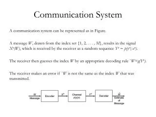
Subject : Communication System Code : 10B11EC514. Dr. Amit Mishra. Syllabus. Evaluation Procedure. Examples of communication system. Block diagram of Communication system. Source originates a message. Example: a human voice, a television picture, a teletype message or data.

E N D
Subject : Communication SystemCode : 10B11EC514 Dr. Amit Mishra
Source originates a message. Example: a human voice, a television picture, a teletype message or data. Input Transducer converted this message into an equivalent electrical waveform referred to as baseband signal or message signal. Transmitter modifies the baseband signal for efficient transmission. Channel is a medium through which the transmitter output is sent. Example: wire, coaxial cable, a waveguide, an optical fiber, or a radio link. Channel acts partly as a filter to attenuate the signal and distort its waveform.
The waveform is distorted because of different amounts of attenuation and phase shift suffered by different frequency components of the signal. (a) Linear distortion (b) Nonlinear distortion Receiver reprocesses the signal received from the channel by undoing the signal modifications made at the transmitter and the channel. Output Transducer which converts the electrical signal to its original form-the message.
Messages Digital messages are constructed with a finite number of symbols. A digital message constructed with M symbols is called an M-ary message. Example: (a) printed English language consists of 26 letters, 10 numbers, a space and several punctuation marks. (b) Morse-coded telegraph message (constructed from a set of only two symbols-mark and space (binary)).
Analog messages are characterized by data whose values vary over a continuous range. Example: (a) the temperature or the atmospheric pressure of a certain location can vary over a continuous range and can assume an infinite number of possible values. (b) A speech waveform has amplitudes that vary over a continuous range.
Modulation • Definition: Modulation is a scheme in which baseband signal is used to modify some parameter of a high-frequency carrier signal. • Need of Modulation: • Requirement of antenna for transmission • To transmit more than one signal on the same channel using multiplexing through FDM (using different carrier frequency) and TDM (using gap between pulse) • To synchronize spectrum of transmitted data and channel
Noise in Channel 1- Manmade (artificial): these could be eliminated via better design -Machinery (ignition of motorbike, car, plane etc.)-Electrical Switches in telephone exchange-Commutator-generator noise in electrical machines (due to repeatedly contact between armature and brushes.) 2- Natural-Atmospheric noise (Lightening discharges) : causing crackles on our radios-Cosmic noise (EM radiations (solar flares), space noise): Noise in Electrical componentsThermal noise: Random free electron movement in a conductor (resistor) due to thermal agitationShot noise: Due to random variation in current superimposed upon the DC value. It is due to variation in arrival time of charge carriers in active devices.Flicker noise: Observed at very low frequencies, and is thought to be due to fluctuation in the conductivity of semiconductor devices
Analog to digital conversion Analog to digital conversion of a signal
Noise Immunity of Digital signal • Transmitted signal • Received distorted signal • Received distorted signal (with noise) • Regenerated signal (delayed)
Power Level: A power level of 0 dBm (sometimes dBmW or Decibel-milliwatts)corresponds to a power of 1 milliwatt. To express an arbitrary power P in watts as x in dBm, or vice versa, the following equivalent expressions may be used: We know: and where P is the power in W and x is the power level in dBm.
A 3 dB increase in level is approximately equivalent to doubling the power, which means that a level of 3 dBm corresponds roughly to a power of 2 mW. For each 3 dB decrease in level, the power is reduced by about one half, making −3 dBm correspond to a power of about 0.5 mW. Example:
Channel bandwidth is the range of frequencies that it can transmit with reasonable fidelity. For example, if a channel can transmit with reasonable fidelity a signal whose frequency components occupy a range from 0 (dc) up to a maximum of 5000 Hz (5 KHz), the channel bandwidth B is 5 KHz. The signal power S plays a dual role in information transmission. First, S is related to the quality of transmission. Increasing S, the signal power, reduces the effect of channel noise, and the information is received more accurately, or with less uncertainty. A larger signal-to-noise ratio (SNR) also allows transmission over a longer distance.
The second role of the signal power S is to make itself exchangeable with channel bandwidth B. If we double the channel bandwidth, the required SNR is just a square root of the former SNR suitable for efficient transmission. But both parameters have their upper limits depending on specific application. Channel Capacity: (Shannon’s equation) C= Channel capacity (bits/second), B=Bandwidth of channel SNR=Signal to Noise Ratio