Download
1 / 45
450 likes | 650 Views
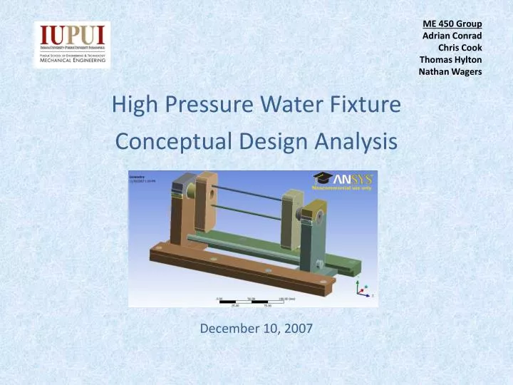
ME 450 Group Adrian Conrad Chris Cook Thomas Hylton Nathan Wagers. High Pressure Water Fixture Conceptual Design Analysis December 10, 2007. Design Objectives. Demonstrate understanding of FEA through ANSYS Workbench.

E N D
ME 450 GroupAdrian ConradChris Cook Thomas HyltonNathan Wagers High Pressure Water Fixture Conceptual Design Analysis December 10, 2007
Design Objectives • Demonstrate understanding of FEA through ANSYS Workbench. • Analysis had to prove that the current design was safe to operate under applied pressures. • Maximum stress would be below yield strength, therefore preventing plastic deformation. • Final analysis would allow for proper modifications to the fixture’s overall design.
Introduction • High Pressure Water Fixture designed to flow water through interior of an airfoil to clean out any extra debris.
Introduction • 4,000 psi water flowing into fixture. • Stainless Steel fixture material. • Arbor adjustability • Fixture Dimensions: - Height: 4.5” - Length: 12” - Width: 5”
Element Types • 186 and 187 type elements • Used for Curved Surfaces • More nodes allows surface conformability 10 Node Tetrahedral Element 4 Node Tetrahedral Element
Utilized Theory • Maximum Displacement • For u, v, & w components • Von Mises Stress
Utilized Theory Contd… • Strain Where: And:
Model Details • Pro/E Model • Assembly of 34 Components • IGES File Creation • Solid Type
FEA Tool: ANSYS Workbench • Why? • Efficient Meshing • Automatic Mesh • Ease of Use for Refinement • Large Contact Edges • Arbor Bottom Edges
IGES File Import (2) Large Contact Large Contacts Swivel Arbor Cap Arbor Long Rods Long Rods Swivel Case Socket Bolt Base Side Base Top
Model Details: Material Stainless Steel AISI 304
Geometry Connections • Default Contact Regions • Need for Fixed Constraints • Large Contact to Threads of 2 Long Rods • Base of Arbor to Socket Bolt • Large Contacts to 2 Swivels • Fixed Support
Defined Loads • Worst Case Scenario • Maximum Pressure • Uniformly Distributed Force • (4000 psi = 27.579 MPa) • Perpendicular to Large Contact Faces
Defined Loads (2) • Ramp Loading of Pressure Forces • Approximation of Quick Turn-On of Pressure Washer
Mesh • Two Different Sizes Used • Relevance Center • Coarse • Fine • Why? • To compare accuracy of displacements and stresses
Mesh (2) • Types of Elements • SOLID 186 • High Order 20-node Brick Elements • SOLID 187 • 10-node Quadratic Tetrahedral (H) Elements • CONTACT 170/174 • Part to Part Interaction for Assemblies • High End Surface to Surface Contact Elements
Coarse Mesh: Holes and Edges • Projected Higher Stresses • Large Contact Holes • Arbor Base Edges • Refinement of Mesh • Number of Divisions • 15 Elements per Hole • Size of Elements • 0.001 m for Edges
Coarse Mesh: Holes and Edges (2) = Hole Refinement = Edge Refinement
Fine Mesh • Relevance Center: Fine • Refinement of Mesh • Number of Divisions • 30 Elements per Hole
Analyzing the Results • Analysis to look at • Total Deformation • Equivalent (von Mises) Stresses • Locate Problem Areas • Comparison of Problem Areas • Coarse and Fine Mesh • Brick and Tetrahedral Meshes of Large Contacts
Total Deformation Fine Mesh Coarse Mesh
Equivalent Stress and Problem Areas Fine Mesh Coarse Mesh Problem Areas
Problem Areas • Threaded Holes Through Large Contacts • Closer Inspection • Brick Mesh • Tetrahedral Mesh • Equivalent Stress • Yield Strength of 205MPa • Tensile Strength of 515MPa
Tetrahedral Meshed Large Contact Equivalent Stress Fine Mesh Max Stress = 3,500 MPa Coarse Mesh Max Stress = 3,500 MPa
Brick Meshed Large Contact Equivalent Stress Fine Mesh Max Stress = 2,000 MPa Coarse Mesh Max Stress = 1,700 MPa
Summary of Results • Total Deformation Seemed Acceptable • Equivalent Stresses Highlighted Problems • Problem Areas • Tetrahedral Meshed Large Contact • Coarse and Fine Mesh – Over yield • Brick Meshed Large Contact • Coarse and Fine Mesh – Over yield • Design Not Acceptable
Design Suggestions • Thicken the two connecting rods • Thread size increase • Large Contact thickness increase • Add additional connecting rod
Impact Statement • High Pressure Water Flow - Successfully clean interior of airfoil - Possibility of injury • Current Design - Inner Rod diameters too small - Further development/analysis on overall fixture • Safety of overall design/operation still a major concern.
References • Moaveni, Saeed. Finite Element Analysis: Theory and Applications with ANSYS, 3rd Ed., Pearson Prentice Hall, Upper Saddle River, NJ, 2007, 30 Oct 2007. • Nema, K., Akay, H.U., Ch 13 Three Dimensional Elements, Department of Mechanical Engineering, IUPUI, Indianapolis, IN, 3 March, 2004, 23 Oct 2007. • http://www.efunda.com/materials/alloys/stainless_steels/ 11/26/07