Download
1 / 68
690 likes | 866 Views
Self-Stabilizing Quad-Rotor Helicopter. Group 7 Daniel Goodhew Angel Rodriguez Jared Rought John Sullivan. Agenda. Project Motivation and Goals Project Specifications System Block Diagram Inertial Measurement Unit and Sensors User Interface Vehicle Body Power Problems and Successes

E N D
Self-Stabilizing Quad-Rotor Helicopter Group 7 Daniel Goodhew Angel Rodriguez Jared Rought John Sullivan
Agenda • Project Motivation and Goals • Project Specifications • System Block Diagram • Inertial Measurement Unit and Sensors • User Interface • Vehicle Body • Power • Problems and Successes • Administrative Details • Questions
General Requirements and Specifications • Weigh around 1kg • Have 12 minutes of flight time • Be able to change motor speed at a rate of 50 Hz • Self Stabilize • Have a camera for video • User controlled from an iPhone • Send status and video data for display on iPhone • Communicate with iPhone 4 times per second
Inertial Measurement Unit Goals and Objectives • Provide data regarding the orientation of the aircraft • Be able to track tri-axial rotations in a timely manner • Easily interface with microcontroller
IMU Specifications and Requirements • Track pitch, roll and yaw • At minimum, have a refresh rate of 50 Hz • Operate off a 610 mAh battery
Selection of Orientation Algorithm • Many approaches available • Simple control loop • Modeling Flight Dynamics • Draw backs • Not accurate enough to provide highly stable flight • Requires extensive modeling of aircraft and environment
Alternative Algorithm Selected: Directional Cosine Matrix (DCM) • Provides accurate orientation tracking • Loosely based of a flight control method developed for planes • Draw backs • Method is limited by the accuracy of the sensors • Gyro drift
DCM Explained • Rotational matrices describe orientation of one reference frame with respect to another • Earth • Aircraft
DCM Explained • The earth’s reference frame is fixed • Each row represents a vector R
DCM Design • Gyro measures rate of change in rad/s Using the kinematics of a rotating vector…
DCM Design • This equation can then be integrated to derive the tracking vector • Integration is done through numerical integration
DCM Design Utilizing numerical integration, our equation becomes… r(0) = Starting vector value = Change in vector
DCM Design • Gyro measurements are taken in the aircrafts frame of reference • Rotations in the earth’s reference frame is equal and opposite rotations in the aircraft’s frame of reference • Thus, we invert the sign of all the measurements
DCM Design • To preserve computational efficiency we bring the first term into the matrix, thus removing one addition per vector • Utilizing these equations, we then present the matrix formulation…
DCM Design: Issues • Gyroscopic drift errors attributed to MEMS based electronic gyroscopes • Accumulation of numerical errors
DCM Design: Solutions • Utilize sensor blending to mitigate gyro drift • Accelerometer is used to correct pitch and roll drift • Magnetometer is used to correct yaw drift • Renormalization of the DCM is used to correct numerical integration error accumulation
DCM Renormalization • Compute dot product of X and Y rows of DCM • This should normally be zero because the X and Y axes are orthogonal • Recall that… • A value other than zero signifies error in measurement
DCM Renormalization To find Z, we utilize the property of the cross product…
DCM: Renormalization • The orthogonal vectors must be scaled to ensure a magnitude of one • Use a Taylor expansion
DCM Drift Correction • Accelerometer corrects pitch and roll drift • Centrifugal Acceleration • Not accounted for • Further testing and investigation needed
DCM: Yaw Drift Correction • Magnetometer is used to correct yaw drift • Produces heading • Reference vector is taken during initialization • Used to produce yaw error
PI Controller • Error values processed through a PI controller
DCM Algorithm Status • Completed • Main DCM update and roll pitch correction coded • To be completed • DCM initialization code • Yaw correction • DCM code testing
Control Board • STM32 • All the IMU components • Two 3.3V voltage regulators, one for analog components, the other for digital • Will have headers to connect to outside components • Have a small area to reduce fabrication cost • Dimensions: 2.2 X 3.0 inches • Originally planned to have two boards fabricated by PCB123 for around $20 after $100 credit • Fabricated for free from Daniel’s employer Intersil.
PCB • PCB completed
Sensor selection: Gyroscope • Originally used a 2-axis and 1-axis analog sensors • New design utilizes a 3-axis digital gyro • ITG-3200 from Inversense
Sensor selection: Accel • Selected ADXL335 • 3-axis analog accelerometer • Readily available from Sparkfun
Sensor selection: Magnetometer • Selected HMC5843 • 3-axis digital Magnetometer • Readily available from Sparkfun • Not tilt compensated
Ultrasonic Sensor • Used for automated landing and takeoff • Displays altitude • Must be able to sense the ground up to 15ft away
Ultrasonic Sensor • Chose to go with the Max Botix XL-MaxSonar EZ0 sensor • Determine the distance by dividing the voltage out by 1024 and multiplying by 3.2mV to find out the range in centimeters • max range of 600cm
Microcontroller Requirements • I2C and 4 ADC channels to receive and convert IMU and range finder data • Timer with four PWM outputs to control motors • UART to communicate with Wi-Fi module • Fast enough to run the DCM and control loop once every PWM period of 20 ms. • Enough memory to store all the code
Microcontroller Selection Selected STM32F103CBT6 • Reasons for Selection: • Has the most processing power • Has a lot of storage • Used in a project implementing DCM • Other Information • ARM Cortex-M3 • Produced by STMicoelectronics • Received free samples from STMicroelectronics
STM32 Development Hardware • A JTAG interface will be used to program and debug the STM32 • Olimex USBTINY • Uses USB Port to interface to PC • Development Board • Olimex STM32-H103 • Inexpensive ~$40 • Uses JTAG • Powered from USB • Small size
Software Development • C used as programming language • STMicroelectrnics STM32 Library • Eclipse used as IDE • OpenOCD used to debug code running on STM32 • Source code compiled with Codesourcery’s G++ Lite GNU tool chain • All software tools are open source and are free to use
STM32 Software • Functions • Completed Functions • void SystemInit(void); //Initializes STM32 clocks • void PeriphInit(void); //Configures STM32 Pins and Peripherals • void IMURead(uint_8 device); //reads and converts the specified IMU component and stores the values in an array • Functions to be Completed • void MotorCmd(uint_8 state); //Function that can start or stop the motors • void UpdateMotor(int motor, uint_16 duty); //Updates the speed of the specified motor • void WifiCmd(int direction); //Receive instructions or send information via UART to or from wifi • void Takeoff(void); //Sets quadcopter to lift-off the ground and hover • void Land(void); //Makes quadcopter slowly lose altitude until it lands
Communication: Options • Wi-Fi vs. Bluetooth Class 1 The Bluetooth had better range for both indoor and outdoor applications. The Wi-Fi device had better Data rates that was more essential to use for the use of sending video to the Iphone. We chose to go with the RN-131 Wifi device by Roving Networks.
Communication Overview • The Copter will communicate through the Wi-Fi transceiver to the iPhone • The iPhone will receive the battery data and also the video data coming from the copter • The iPhone will send the copter the controls that the user is inputting
iPhone Interface • An iPhone will be used to control the Quad-copter through an iPhone application • Will be using the Touch based functions of the iPhone to control the copter • Will show a live video stream coming from the copter
Software • iPhone application is written in Objective C • Objective C is an object oriented version of C by Apple • The application is developed using Xcode IDE and through the Interface Builder • The Interface Builder provides easy design capabilities such as drag and drop functionality
Package Structure • From iPhone to Copter • LXX RXX BXX • Left Slider Value, Right Slider Value, Bottom Slider Value • From Copter to iPhone • Altitude of copter • Video data
Difficulties • The only major difficulty encountered to date was getting the I2C communication to work which has been resolved.
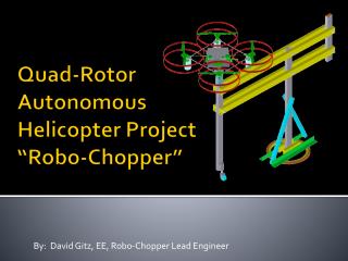
Body • Specifications • Under 1 kg • 25” x 25” x 10” • Aluminum Frame • Lightweight • Reasonably priced • Impact resistant