Download

1 / 4
780 likes | 2.74k Views
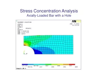
Stress Concentration. In almost engineering components and machine have to incorporate design features which introduce changes in thin cross-section.

E N D
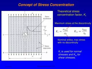
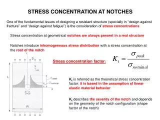
Stress Concentration • In almost engineering components and machine have to incorporate design features which introduce changes in thin cross-section. • Changes in cross section causes localized stress concentrations and severity depends on the geometry of the discontinuity and nature of the material. • Stress concentration factor, • Kt = Smax/Sav • Smax, maximum stress at discontinuity and Sav, nominal stress. • Kt, value depends only on geometry of the part. • Applies to brittle & notch sensitive materials. Should consider when using high-strength, low ductility, case-hardened & / or heavily cold work materials.
Stress Concentration • Stress concentration in fatigue. • Kf, fatigue stress concentration factor, • Kf = endurance limit of notch free • endurance limit of notched part • Notch sensitivity factor, q = Kf - 1 • Kt - 1 • Generally , q 1 as material strength increases and sensitive to notches. • Kf = Kt • q also depend on component size. • Stress-raiser, dangerous in larger masses.
Stress Concentration • Guidelines for design. • Abrupt changes in cross-section should be avoided. • Fillet radii or stress-relieving groove should be provided. • Fig. 11.3(d) • Slot and grooves should be provided with generous run-out radii and with fillet radii in all corners. Fig. 11.3(b) • Stress relieving grooves or undercut should be provided at the end of threads and splines. Fig. 11.3(c) • Sharp internal corners and external edges should be avoided • Weakening features like bolt and oil holes, identification marks, and part number should not be located in highly stressed areas. • Weakening features should be staggered to avoid the addition of their stress concentration effects, Fig. 11.3(d)