Download
1 / 37
370 likes | 476 Views
Status of a Cryogenic System for J-PARC Neutrino - Availability, Tritium creation, Volatilization of the ammonia etc. -. KEK : Y. Makida , H. Ohata , O. Araoka , M. Iida T. Ogitsu , N. Kimura, T. Okamura, T. Nakamoto , K. Sasaki, M. Iio , M. Yoshida. Contents.

E N D
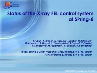
Status of a Cryogenic System for J-PARC Neutrino- Availability, Tritium creation, Volatilization of the ammonia etc. - KEK:Y. Makida, H. Ohata, O. Araoka, M. Iida T. Ogitsu, N. Kimura, T. Okamura, T. Nakamoto, K. Sasaki, M. Iio, M. Yoshida
Contents • J-PARC and T2K Overview. • Cryogenic Plant for T2K. • Status of Cryogenic Plant. • History and Rate of Operation • Initial Failure at Turbine and Pump • Watching Impurities and Unexpected Volatilization . • Creation of Tritium and Radiation Control • Conclusion
J-PARC (Japan Proton Accelerator Research Complex) Hadron Experimental Facility Material and Life Science Facility Transmutation Experimental Facility (in future) Apr., 2009 Neutrino Beam Neutrino Facility To Super - Kamiokande Nov, 2007 3 GeV Main synchrotron 1500 m circ., 25 Hz 30 GeV (in future 50GeV) 3 Gev rapid cycle synchrotron (RCS) 350 m circ. , 25 Hz Linac 330 m Dec, 2008 MR beam Jan, 2007, 181 MeV The J-PARC accelerator complex consists of 3 accelerators, a linear accelerator, a rapid cycle synchrotron (RCS, 3GeV) and a 50 GeV (now 30 ) synchrotron. Each accelerator provides a high intensity beam for the experimental facilities (materials and life science, hadron physics, neutrinos, transmutation). The secondary particles, such as neutrons and mesons as well as neutrinos, are produced by bombarding a target with the proton beam.
Purpose of T2K experiment • The T2K (Tokai to Kamioka)experiment is a neutrino-oscillation experiment to study nature of neutrinos. • Artificial neutrino beam generated in the J-PARC is shoot toward the 50kton water Cherenkov detector, Super-Kamiomande, which is located about 1000m underground in Kamioka mine (Gifu) and is 295km away from Tokai. • http://t2k-experiment.org/ http://www-nu.kek.jp/jhfnu/index_e.html
T2K neutrino facility in J-PARChttp://j-parc.jp/Neutrino/en/nu-facility.html Target-Horn System Target Station MR Muon Monitoring Pit Final Focusing Section 295km to Super-Kamiokande Nu Preparation Section 100m 30 GeV (50 GeV) SC combined funcmags Beam Dump Decay Volume Near Neutrino Detector 5 • P beams accelerated up to 30 GeV are directed westward through the Primary Part . • A string of SC. Mag is a core part in the Primary Part. • P collide with a graphite target and produce -mesons, which decay into neutrinos.
Present status of T2K History of accumulated proton number and beam power improvement 20kW, upto240 kW 65x1019 for physics analysis HD hall radiation accident Electron-neutrino candidate in Super Kamiokande • Although two long shut-down periods due to an earthquake and a radiation accident, T2K resumed data taking. Statistic of P beam became enough to announce its experimental result. • The international T2K collaboration announced a definitive observation of muon neutrino to electron neutrino transformation on July 2013. • T2K saw its first event in antineutrino beam mode on June 2014.
Contents • J-PARC and T2K Overview. • Cryogenic Plant for T2K. • Status of Cryogenic Plant. • History and Rate of Operation • Initial Failure at Turbine and Pump • Watching Impurities and Unexpected Volatilization . • Creation of Tritium and Radiation Control • Conclusion
Primary line components - One string of Superconducting Magnets - The neutrino beam line has a bending section with a radius of 105 m, where single string of 28 superconducting magnets has been installed. The magnet design is very unique. It has a combined function of 2.6 T dipole field with 19.6 T/m quadrupole field gradient by a left-right asymmetric distribution of conductors. 8
Cryogenic Plant overview Cryogenic devices, 4 He tanks, 1 LN2 CE, a compressor, a cold box, a sub-cooler and a current lead box, are set on surface. The magnets are at -12 m under ground andcoolant SHE is transported between them. Pacific Ocean (5m Tsunami arrived) LN2 CE He Tank S.C. Magnet MCP, CB, Sub-cooler, CLB
Overall Layout (Ground Plan) Magnet String & Transfer Line Inventor 3900 ℓ, Cold mass 225 ton(Fe) 90 m transfer line with SC bus Heat Leak 220 W + Beam Loss max 150 W Neutrino Beam Line Superconducting Magnet Arc in main tunnel at -12m level Radius 105m, Length 150m Main Synchrotron Recovery Vessel (for Quench) As Storage Vessel for Inventory Volume 100m3×3 Cold Box、Subcooler SHE Max300 g/s 4.5 K LHe pot : 800 ℓ C/L flow : 1 g/s Superconducting Magnet 10 m Main Compressor (MCP) : 570 kW, 1.4 MPa, 150g/s LN2: 20000 ℓ Only pre-cooling & cold purification 18000 ℓ/day @ pre-cool 300 – 100 K Buffer Vessel (for MCP) Volume 100m3×1
Conceptual Flow Diagram @ excitation LN2 is consumed for pre-cooling and gas purification. A cascade refrigerating system , composed a Claude cycle refrigerator with a centrifugal pump , supplys 4.5 K, 0.4 MPa, 300 g/s She. Turbine flow goes through radiation shield cooling line in the magnet . 1.4MPa, 150 g/s He gas is supplied by the compressor. 70 g/s flow expands and works at turbines, and the rest expand at JT valve in the sub-cooler.
Power saving mode. Refrigerator capacity 1500 W need the 900 W offset by using LHe level control heater. Saving refrigerator capacity by reducing unloader and supply pressure results in lower power consumption at the compressor. Saving 1.5 MYen/month
Contents • J-PARC and T2K Overview. • Cryogenic Plant for T2K. • Status of Cryogenic Plant. • History and Rate of Operation • Initial Failure at Turbine and Pump • Watching Impurities and Unexpected Volatilization . • Creation of Tritium and Radiation Control • Conclusion
History and Rate of Operation 6/5 7/3 17/5 15/3 11/12 8/12 4/12 8/12 FY2012 FY2011 Earthquake 11/3 • After MSS Miss Trigger trouble is solved, Nu cryogenic system has caused no interruptions of T2K experiment. • Rate of operation (availability) is beyond 0.99. • Although cryogenic system did not stop, some devices did abnormal movement. It was only lucky.
History and Rate of Operation FY2013 FY2014 J-PARC operation was not admitted until improved radiation management was established. HD Radioactive Material Leak Accident on 23/May • About HD radiation material leak accident please refer • http://j-parc.jp/HDAccident/HDAccident-e.html • To restart J-PARC operation, Radiation control management became severe. • Nu cryogenic facility and its maintenance method were examined in radiation evaluation committee. • T2K experiment resumed on April 2014.
Contents • J-PARC and T2K Overview. • Cryogenic Plant for T2K. • Status of Cryogenic Plant. • History and Rate of Operation • Initial Failure at Turbine and Pump • Watching Impurities and Unexpected Volatilization . • Creation of Tritium and Radiation Control • Conclusion
Notches in Turbine • We found some notches at 2nd turbine blades by the visual inspection after 2009 autumn operation. • We observed abnormal start movement of 2nd turbine. • LINDE TED turbine needs bearing gas supply during only start-up. And bearing gas stops, after the rotation reach to normal speed. • But 2nd turbine could not start with bearing gas, and it could start when bearing gas stopped. • Once start-up, 2nd turbine rotated normal condition during the beam operation, and cooling power did not degrade. • Measured mechanical strength of the turbine material is rather low. • Linde also reported that the bearing gas pressure at 14 bar in Nu cold box is higher than its design pressure of >10 bar in standard liquefiers. • New turbine made with inspected material was set. • Pressure reducing valve was installed into the bearing gas supply line. Remade 2nd Turbine and 1st Turbine PRV addition into bearing line HP CP MAG LP
Rubbing of SHE pump • We found burrs on the pump impeller blades by the visual inspection after 2010 autumn -> 2011 winter operation. • We heard abnormal large and shrill noiseduring the operation. • But flow rate of 300 g/s at nominal rotation improved 310 g/s. • So, the operation continued. • Lower position of the pump impeller caused scratch of the impeller blades with the pump housing. • New tool and gage to set the blade at the design position are prepared. Cold bearing is Exchanged annually by Taiyo Nippon Sanso, Main contract of Nu cryogenics . And removed bearing is inspected by Barber Nichols to analyze its operation life. Tuning Bolt of Rod Length Cold Bearing
Contents • J-PARC and T2K Overview. • Cryogenic Plant for T2K. • Status of Cryogenic Plant. • History and Rate of Operation • Initial Failure at Turbine and Pump • Watching Impurities and Unexpected Volatilization . • Creation of Tritium and Radiation Control • Conclusion
Watching and measuring impurities • Inner Detectors (Measured gas go to the LP line) • Dew-point meter : MICHLL Ins. Water detection < - 60 ۫C ( before cool down ), -90 ۫C (usually) • Discharge light spectrometer : KEK original N2, < 1 ppm • Gas chromatograph : SHIMAZU → LINDE multi component detector N2, O2, CO, CO2 < 1 ppm • Gas sampling ( at warm-up 25 K ) • Quadruples mass spectrometer : ULVAC & JAEA H2 < 1 ppm H2 from polymers in the magnets by beam irradiation. • Liquid scintillator : Radiation Control Equipment HT < 7 Bq/cc, HTO < 5 mBq/cc (Radiation control criteria) Tritium transmuted from 3He
Oil separation check Screw Compressor 1st Separator Demister Separation 2nd & 3rd Separator Filter Element Coalescence 4th Separator Active Charcoal Adsorption 5th Separator Molecular Sieve Adsorption Water Cooler Oil must be ≦0.001vol.ppm Oil check sampling annually. Daily check through sight glass. Oil return Solenoid valve with Counter and Action signal Filter element selection is important. Activity of DOMINICK HUNTER is short. This element caused RIKEN Oil diffusion accident. TAIHEIYOU filter is activate longer. So, filters in 2nd separator were exchanged. Level Switch Sight Glass Controller Counting Interval check Action Signal Controller checks oil return valve action interval. If the interval become longer, that means filter elements are saturated.
Unexpected Volatilization : Ammonia from Magnet Ammonia Origin Glass-reinforced Phenolic Thermosets Rin=102 mm, t=20 mm, L= 100 mm *PM9640 by Sumitomo Bakelite, Arisawa Atmosphere Atmosphere • We found that irritant odor in vent helium gas from the magnet at maintenance. • Gas analyzing showed that the odor material is ammonia. • Search found the plastic spacer is its origin. • Why the Nu refrigerator was not blocked up? • Molecular Sieve (Crystalline Zeolite) in 5th oil separator can adsorb large quantity of ammonia. • 5th separator has large enough quantity of MS, which can adsorb 79 kg ammonia. • And MS can be re-activate by heating at 150 ℃. Pump Ammonia Detector He Recovery MS (13X) Adsorb Thermo-meter Dew point mater Heater He + 100 ppm NH3 to watch adsorption He for carburation N2 gas for reactivation
Contents • J-PARC and T2K Overview. • Cryogenic Plant for T2K. • Status of Cryogenic Plant. • History and Rate of Operation • Initial Failure at Turbine and Pump • Watching Impurities and Unexpected Volatilization . • Creation of Tritium and Radiation Control • Conclusion
Measurement Record of Tritium (HT & HTO) HT (BP 25K) and HTO inside MAG @ Beam Time -> Sampling at > 25 K, @ Return from MAG • Sample gas is analyzed by Liquid scintillater with precision of 5Bq/L. • Analysis is done at RT, AP. Larger Beam Power may produce more tritium. << A. Limit Regulation * Allowable limit in discharging gaseous radioactive waste Law Concerning Prevention from Radiation Hazards due to Radio‐Isotopes, etc. (≈ ICRP90) Radiation Management in J-PARC require • Gaseous waste must be vent through authorized vent stack with radiation monitor. Even small gas vent from maintained equipment must follow the guideline. • The work place, where gaseous waste is vent, is set as a radiation management area temporally.
Same Operation and Modified Maintenance due to Tritium But Radiation Management in J-PARC accept • Nu cryogenic system, which is designed and is inspected by High Pressure Gas Regulation, holds enough air-tightness to prevent tritium leakage. • Consequently, Nu cryogenic area on surface need not become radiation management area permanently. It is only set, when the helium gas part is exposed. Otherwise Vent Stack Air Temporal Radiation Management Area C/L Box Tank Subcooler Evaporator Tank CB Evaporator Air Tank Yard Cryo. Room Tank Oil Separator MCP
Guide Line of Temporal Radiation Management Cryogenics Room = Temporal Backup Seal Temporal Vent Line Existing Vent Stack Temporal 1st Seal Backup Seal Vac. Pump Radiation Monitor Sub- Cooler CB MCP Tank CL BOX Surface Under Ground Radiation Management Magnet He Vent Line Beam Pipe Vacuum Vessel 1 mm Metal Mesh 0.1 mm Metal Mesh
Actual Method : Filter Exchange at 2nd,3rd Oil Separator Setting Management Area Radiation Safety Check By gas sampling and smearing. Analysis takes 1day 400 m3/h blower exhausts air from the room to the vent line. Oil Filter Exchange 1st seal Oil Separator Unit is covered by an air-tight plastic sheet room. Backup seal Cryogenic Room becomes radiation management area. Radiation Safety Check By smearing. Analysis takes 1day Cancel Management Area
Actual Method : Relief Valve Exchange at outdoor Tanks RV vent RV Setting Management Area Radiation Safety Check By smearing. Analysis takes 0.5day Stop Valve He must be vent before RV removal Wrench is kept inside plastic bag as 1st seal. Back up seal is rope. Rope set management area . Rope is back-up seal ??? Radiation Safety Check By smearing. Analysis takes .5day Removed RV Smear Inspection Send RV to maker for calibration Cancel Management Area
CONCLUSION • After initial troubles were solved, Nu cryogenic system has been stable since FY2012 autumn. • It was not expected that volatilization of the ammonia from the magnet, but fortunately, molecular sieve in the 5th oil separator can adsorb a gross quantity. • Tritium of 40 Bq/L has been detected in refrigerant. In spite of lower value than its allowable limit of 7000 Bq/L, Nu cryogenic operation and maintenance method were examined in radiation evaluation committee. • Helium vent must be through authorized line and stack after radiation measurement. Fortunately vent line from RV and the vacuum pumps had been constructed. Gas monitor and metal filters were installed into the vent line additionally. • Some maintenance works, RV and oil filter etc. exchange, need setting of temporal radiation management area and complicated procedures.
Conceptual Flow Diagram @ excitation SHE pump outlet is connected with the inlet of JTV. The pressure in this connection line is kept at 0.4 MPa by the JTV. This control scheme spontaneously complements the current leads cooling gas which falls out from the pumped circulation. A pair of cooling gas flow for the current leads is divided from the SHE supply line simply. SC cables directly enter the SHE line
External set of a dryer and a cryogenic purifier is installed, because large amount of moisture and air from magnet electric insulator were predicted. The capacity of this purification unit is large enough for the 1000 ppm inventory. • Impurities in helium gas was actually removed in two days before cooling down, so the rate of operation of the dryer and the purifier is very low.
Effort of Power Saving Mode Saving 1.5 MYen/month, 55 ton CO2/month
Conceptual Flow Diagram @ pre-cooling CB&SC pre-cooling Gas transport The cooling He gas circulation through the magnets is driven by the compressor. The pump circulation is bypassed for its pre-cooling. Magnets is cooled down for 8 days. The shield circulation is driven by the compressor, too. Magnet Pre-cooling Shield Pre-cooling
Conceptual Flow Diagram @ Quench Liquefaction Pump Protection Gas Recovery C/L Cooling At quench, the pump circulation quickly switch to the bypass line and is isolated from the magnets. The quenched magnet pressure is released to the storage tanks through the exhaustion lines directly. Quench Emergent Exhaustion CP 0.45MPa Shield Cooling
Tritium Estimation at 1W/m beam Loss( in case of All beam loss in the SC ) • After 4000 h 1w/m loss • Beam Tube Periphery • 180 Bq/cc * 5 litter • Cooling Hole • 25 Bq/cc * 10 litter • Press Shoulder etc • 10 Bq/cc * 15 litter • End Space • 50 Bq/cc * 40litter • 3He to tritium • 7 Bq/cc* (5+10+15+40) litter • Total • 54 Bq/cc