Download
1 / 15
170 likes | 449 Views
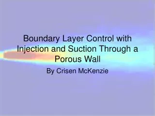
Fluid Flow: Establishing Boundary Conditions. Objectives. Section 5 – Fluid Flow Module 3: Boundary Conditions Page 2. Understand the workflow to perform numerical analysis. Identify system boundaries. Examine types of boundary conditions (BCs). Understand hydraulic diameter.

E N D
Fluid Flow: EstablishingBoundary Conditions
Objectives Section 5 – Fluid Flow Module 3: Boundary Conditions Page 2 • Understand the workflow to perform numerical analysis. • Identify system boundaries. • Examine types of boundary conditions (BCs). • Understand hydraulic diameter. • Learn how Initial conditions make an impact. • Identify regions of high gradients. • Understand grid independence. • Study the importance of correct boundary conditions. • Learn from an example: CFD analysis of Couette Flow (steady state)
Workflow Section 5 – Fluid Flow Module 3: Boundary Conditions Page 3 • Once a user gets started with numerical analysis, the following steps will have to be taken: • Establish the flow characteristic (e.g., external, internal, steady, unsteady, laminar, turbulent, compressible, incompressible). • Establish boundaries of the flow domain as well as the objects inside the domain. • Determine the extent of the flow domain (hydraulic diameter and characteristic length) for external flows. • Identify regions with high gradients. • Achieve grid independence.
Types of Boundaries: Part I Section 5 – Fluid Flow Module 3: Boundary Conditions Page 4 • Generally a CFD software application defines the following boundary conditions: • Inlet/Outlet • Wall • Fluid cannot pass through • No-slip • Wall roughness can be defined • Wall movement can be assigned • Porous Medium • Some fluid can pass through depending upon porosity • Periodic Boundary Condition • Can be applied for a regular geometrical pattern, such as flow across pipes Walls Outlet Inlet
Types of Boundaries: Part II Section 5 – Fluid Flow Module 3: Boundary Conditions Page 5 Free Surface • Fan Surface • Provides a sudden jump in velocity or pressure • Free Surface • Unbounded surface such as in open channel flows • Symmetric • Can reduce domain size to half or even a quarter if axis of symmetry exists • Axisymmetry • Flow in tanks, pipes and circular geometry can make use of axisymmetric boundary condition Wall Wall Wall
Identification of System Boundaries Section 5 – Fluid Flow Module 3: Boundary Conditions Page 6 • In the case of internal flow, it is easier to determine system boundaries. • The fluid extent or physical wall determines the boundaries. • For an external flow system the extent of boundaries has to be identified, as the surrounding fluid is limitless. • In the case of external flow, system boundaries should be confined to the region of influence of the object with respect to the flow. • For external flow cases, hydraulic diameter and characteristic Length help us determine the system boundaries.
Understanding Boundaries Section 5 – Fluid Flow Module 3: Boundary Conditions Page 7 • When selecting boundaries, consider that fluid entering the domain must be equal to the fluid exiting the domain. • Inlet and outlet boundary conditions must be selected for steady flow. • Conservation of mass and energy must be accounted for, or else divergence will result for steady flow / equilibrium problems. • Special cases include fluid confined inside a closed object (e.g., sloshing in tanks) where flow occurs due to movement of the object. • In such cases inlet and outlet conditions are not required. • Once the extent of a domain is worked out, geometry for the domain can be modeled in CAD software. • Simplification is sometimes required to eliminate small geometrical details that can increase mesh complexity.
Hydraulic Diameter and Characteristic Length Section 5 – Fluid Flow Module 3: Boundary Conditions Page 8 • In fluid flow, hydraulic diameter is the estimated length of a non- circular conduit that would be equivalent to a circular duct in terms of influence on flow behavior. • Similarly, hydraulic diameter (HD) and characteristic length (CL) can also be used for external flow to determine the domain size. • A general rule of thumb is that for flow around a bluff body, 5 CL all around the body and 8 CL behind the bluff body should be added to the domain size. • Formulae are available to calculate the HD of various shapes. • For instance, the HD of a square is given as DH= 4 a b / (2 (a + b),where “a” is the length and “b” is the breadth of the rectangle.
Initial Conditions Section 5 – Fluid Flow Module 3: Boundary Conditions Page 9 • Initial conditions may not have an effect on the outcome of the solution; however, a good initial estimate can reduce the number of iterations required. • At times, flow analysis from a separate simulation run can provide initial conditions for a subsequent simulation. • For instance, a flow simulation for steady state conditions inside a pipe with a fixed velocity of 5 m/s can provide initial conditions for a transient flow analysis for the same pipe for a case where velocity increases from 5m/s to 10m/s.
Regions of High Gradients Section 5 – Fluid Flow Module 3: Boundary Conditions Page 10 • High pressure and velocity gradients can occur inside the flow domain. • Such regions become important because they can affect the outcome of the final result. • It is important to have a refined mesh in such regions so that the flow gradients are captured appropriately. • It is important that cells in this region should be regularly shaped and unskewed. • An experienced user can identify the regions of importance. • Fluid regions of converging, diverging or bending sections in internal flow and the near-wall and wake regions in external flow should have finer meshes.
Grid Independence Section 5 – Fluid Flow Module 3: Boundary Conditions Page 11 • Grid independence is said to have been achieved when further refinement in a grid does not result in notable improvement in the accuracy of a solution. • Regions where high gradients exist are critical, and grid refinement in those regions can improve the accuracy of the results substantially. • If a problem setup has reached grid independence, it can act as a template for investigating what-if scenarios. • Pilot simulations can be run to identify regions of importance. • The meshes in these specific regions can then be refined.
Importance of Boundary Conditions Section 5 – Fluid Flow Module 3: Boundary Conditions Page 12 • It is crucial for accurate analysis to identify the extent of the domain boundary and type of boundary. • For internal flows, the domain size is generally the size of the system. • Examples: pipes, pumps, mixing tanks • For external flow, domain boundaries are not distinctive and must be identified by the user. • Available computation resources and required accuracy are factors. • Examples: flow over a car, train, submarine or bluff body • Due to limitations in computing resources, simplifications are often made to geometry that affects boundaries. • Example: External geometry of an automobile may be simplified with small protrusions removed and depressions patched to save computation time.
Video Example: CFD Analysis of Couette Flow (Steady State) Section 5 – Fluid Flow Module 3: Boundary Conditions Page 13 • The CFD analysis of Couette flow using Autodesk Simulation Multiphysics has been described in a two-part video: • The first part explains the problem, setting up of the flow domain, meshing and the application of boundary conditions. • The second part is about domain discretization and creation of algebraic equations and is relevant to this presentation. Y u0 Moving Plate X Stationary Plate
Summary Section 5 – Fluid Flow Module 3: Boundary Conditions Page 14 • For any analysis, exact or numerical, Boundary Conditions must be defined. • In fluid flow, different types of boundary conditions are employed, of which the most common are inlet/outlet, wall and velocity. • Conservation of mass must be taken into account when selecting boundaries. • For instance, divergence in the numerical solution would occur with a system where only an inlet is defined without an outlet, with flow restricted inside by an impermeable and non-flexible wall.
Summary Section 5 – Fluid Flow Module 3: Boundary Conditions Page 15 • For external flow systems, hydraulic diameter and characteristic length help establish domain extent. • Boundary conditions must be defined by the user. • The closer the boundary conditions are to real life cases, the better and more accurate the solution.