Download
1 / 25
250 likes | 382 Views
Longitudinal Dynamics in the ALICE Injection Line. Julian McKenzie Frank Jackson, Yuri Saveliev , Peter Williams… ERL 2011 Workshop KEK, Tsukuba, Japan 20 October 2011. ALICE Overview. Nominal Gun Energy 350 keV Injector Energy 8.35 MeV Circulating Beam Energy 35 MeV

E N D
Longitudinal Dynamics in the ALICE Injection Line Julian McKenzieFrank Jackson, Yuri Saveliev, Peter Williams… ERL 2011 Workshop KEK, Tsukuba, Japan 20 October 2011
ALICE Overview • Nominal Gun Energy350 keV • Injector Energy 8.35 MeV • Circulating Beam Energy 35 MeV • RF Frequency 1.3 GHz • Bunch Repetition Rate 81.25 MHz • Nominal Bunch Charge 80 pC • Average Current 6.5 mA (Over the 100 ms Bunch Train) Operational modes: • IR-FEL • THz • EMMA (ns-FFAG) • Compton back-scattering • Many more…
Injector Layout DC electron gun JLab FEL GaAsphotocathodes buncher Booster cavities solenoid solenoid 0.23 m 1.3 m 1.67 m 2.32 m 3.5 m 5 m
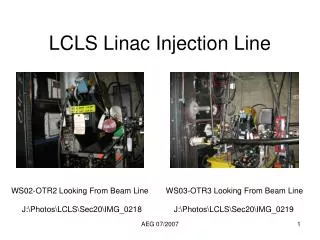
ALICE Injection Line • ~10m between booster and linac • Layout restricted by building • Only 1 screen after 3 dipoles and 6 quads...
Operational parameters • Gun voltage limited by ceramic – replacing in winter shutdown. • Linac energy and bunch repetition rate is limited by beam loading, replacing cryomodule with new DICC module in winter shutdown.
Booster issues • Booster cryomodule consists of two 9-cell TESLA type cavities • Each ~ 1 m long and designed for electrons with β=1 • We inject at 230 keV and accelerate to 4 MeV in first cavity • Therefore phase beam sees in each cell is completely different • Beginning of BC1 completely dominates dynamics
BC1 cresting issues Experimental data ASTRA simulation Blue = maximum energy Red = central energy Green = minimum energy • Measure BC1 crest by observing beam after first dipole • At operational bunch charges (40-80pC), beam can be very large on screen At 1 pC, curve symmetric and crest matches ASTRA
Energy Almost decelerate the beam completely at start of BC1
Energy Almost decelerate the beam completely at start of BC1
Energy spread Red = after BC1 Blue = after BC2 BC2 phase used to compensate energy spread from first cavity by rotating the chirp in longitudinal phase space
Energy spread measurements ASTRA Simulations
Longitudinal phase space BC1 Phase: Red = -20° Green = -10° Blue = -5° “Hooks” and other features can easily develop
Bunch length ~27 ps laser pulse formed by stacking 7ps Gaussian pulses Doesn’t provide ideal flat-top Laser temporal profile in 2008 • Bunch length expands after gun due to space charge. • Buncher cavity only reduces bunch length down to same level as initial • Further compression occurs in BC1
Bunch length measurements Use LC2 and screens after dipoles Use BC2 and screen after dipole Streak camera Electro-optic
Zero-crossing method: • Use second cavity in cryomodule at zero-cross phase to give energy chirp • View energy spread as transverse spread after dipole • Take images at both zero-crosses • Problems: • Minimising beta for each image • Jitter • Non-Gaussian beams • Background noise (post-linac only) • Reconstructing transverse beam profile from numerous screen images stitched together Small injector beam image Post-linac beam image
Buncher power scans Lines = simulation Dots = measurements BC1 set to -10 Bunch charge 40pC Uncorrelated energy spread found by operating BC2 at zero-cross to minimise energy spread by compensating for the chirp.
Measurement repeatability: Same machine setup used for these measurements: Buncher power 0.53kW BC1 phase -20°with 4 MeV energy on-crest Energy spread method: chirph = Blue = booster Red = linac
BC1 phase vs bunch length Lines = simulation Crosses = measurements Booster Buncher power = 0.53kW Bunch charge 60pC Bunch length consistently shorter at linac than booster Linac
Compression in booster to linac transport line • Total R56 of injection line ~30mm • Very small compared to 28cm in chicane • However, it is of the right sign to compress bunch if chirp not fully compensated by BC2 ELEGANT simulations can show compression but don’t take into account all effects, space charge still important at 6 MeV
Elegant simulations Unchirped bunch Black = After booster Red = Before linac Chirped bunch
Elegant with LSC on Unchirped bunch Black = After booster Red = Linac, no LSC Blue = Linac, with LSC Chirped bunch
Velocity de-bunching between booster and main linac After booster Before linac ASTRA simulation (for long drift, doesn’t include dipoles)
After booster Even with fully rotated bunch, can have adverse effects if phase-space has “hook” Before linac ASTRA simulation (for long drift, doesn’t include dipoles)
Summary: • Injector dynamics complicated by reduced gun energy and long multi-cell booster cavity • Can achieve bunch length and energy spread needed for FEL operations • Bunch length measurements show < 2mm (6ps) rms bunch length in injector • Measurements indicate reduction bunch length between booster and linac • Simulations/measurements still not fully understood – more investigations under way • Have to be careful with “features” in the longitudinal phase space