Download
1 / 28
280 likes | 501 Views
RPC Application on Horton and Model Railway Computer Control Centre. Stephen Parascandolo [M1161] Paul Durell Beckenham and West Wickham MRC. Contents. About Us Horton Crash Course in UK Railway Signalling RPC Application on Horton MRCCC Software Automatic Train Protection

E N D
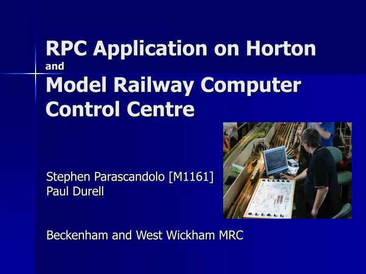
RPC Application on HortonandModel Railway Computer Control Centre Stephen Parascandolo [M1161] Paul Durell Beckenham and West Wickham MRC
Contents • About Us • Horton • Crash Course in UK Railway Signalling • RPC Application on Horton • MRCCC Software • Automatic Train Protection • Computer Assisted Cab Control • Future Developments • Questions / Discussion
Stephen Parascandolo • Brunel University Graduate • BEng (Hons), First Class, Computer Systems Engineering, 2003 • Senior Signalling Engineer • GE Transportation Systems • Design and configuration of modern VDU based signalling control centres and train describers • Database Manager • Member of Beckenham and West Wickham MRC • Developed Horton since 1993 • Introduced signalling and electronics • Webmaster of www.tramlink.co.uk • MERG Member since 2000
Paul Durell • Senior Signalling Engineer • British Rail/Amec/Balfour Beatty/Network Rail 1987 to present • Maintenance and Rapid Response to signalling systems, including On track points, track circuits and signals. Relay Room based control systems including Relay and electronic remote control via FDM and TDM • I.R.S.E. Licensed Team Leader, Maintainer Fault Finder. • Member of Beckenham and West Wickham MRC • Involved in rebuild of Horton since 2003 • Developed CACC, PSUs and Controllers • Wired Panel, Relay Room and some baseboards • Requires MERG Membership Form!
Horton • 32’ x 10’ Modern Image OO • All Round Viewing • 6 Controller Cab Control • 31 Main Signals (12 Shunt Signals) • 68 Point Ends • 142 Track Sections (88 Track Circuited)
Modern UK Signalling Crash Course! • Signals provided to protect against collisions • Protecting Junctions • Protecting the train ahead • Drivers to obey signals • Signallers to ensure safety and correct routing of trains
Routes • Exist from an Entry Signal to the next signal the train will come to, the Exit signal. • Four Types: • Main • Warner • Shunt (Permissive) • Call On (Permissive) • Named after Entry Signal • Letters for each destination, starting from the left
Routes • Signaller Calls Route by pressing ENtry Signal, followed by EXit signal (NX). • Interlocking checks • Route exists between Entrance and Exit • No Conflicting Routes • Any Points Required to move are Free • Route is Clear – using Track Circuits (unless permissive) • Route then Calls Points • Route Locks (White Lights displayed on line of route) • Signal may clear – but that is up to the signal! • Signaller Can Cancel (Pull the Entrance Button) or • TORR (Train Operated Route Release) – Route Releases automatically as train traverses Route. • Operation of an Auto Button, prevents TORR from taking place
Signal Types • Main • If showing proceed aspect (not Red), line is clear to the next main signal. • Subsidiary/Shunt • Line may be occupied – driver to be able to stop within distance that can be seen • Controlled • Route must be set by signaller before clearing and track circuits clear • Automatic • Will clear if track circuits are clear • Main signals only
Points Lie • Normal • Usually the main route, or the safest position. • Points always drawn in the Normal Position on plans and panels. • Reverse • The opposite of Normal Point Key • Normal • Point Locked Normal • Centre • Point free for Route Setting • Reverse • Point Locked Reverse
Track Circuits and Signals • Track Circuits are used for train detection • Track Circuits prove a section of track is clear. • For Model Railways, we have the FTC • Track Circuits used to control signal aspects • Signal spacing designed to ensure a driver can run at line speed under green signals. • Distance from sighting the first cautionary signal to the Red signal must be at least Braking Distance.
RPC Application on Horton • See Technical Bulletin G16/81
A fully signalled model railway is complex. Don’t build it before designing it! Track Layout – Consider Operations Signalling Plan Cab Switching Requirements System Design RPC Stack RPC Addresses Cable Schematics (finalise what is on each baseboard first) Tag Strips Control Panel Design Documentation Control Centre Data Build / Install Test Rework Design > Install > Test
Model Railway Computer Control Centre History • Started as a Brunel University Project in 2002-3 • Received a Final Year Project mark of 76% for MRCCC • Enhanced the application since, following the expansion of the Horton RPC application • Written in MS Visual Basic .NET 2003 • Open Source Three Modes • Design Mode • Test Mode • Operate Mode Basics Grey Track = Normal White Track = Route Locked Red Track = Track Occupied • Indication and Control almost compliant with Network Rail Standards GK/RT/0025 and RT/E/S/17504 for VDU based control systems MRCCC Website http://www.bwwmrc.co.uk/mrccc
Model Railway Computer Control Centre Current Features • VDU control of Model Railway signalling on a PC. • User Configurable screen layout and interlocking conditions. Configuration is via Windows dialog boxes, which should be understood with a little signalling knowledge, and not with any kind of scripting language requiring computing knowledge. • Full and comprehensive validation of all user-configured data with feedback at each stage on exactly why a layout is invalid or what is wrong with an entry just made. • Test Mode provided for offline testing (without connecting the layout) of the full interlocking including the ability to simulate user and layout inputs and monitor all states within the system. • Entry-Exit (NX) Route setting by mouse, calling all points as required. • Auto Working buttons. • Full automatic aspect sequencing for 2-, 3- and 4-aspect colour light signalling (only basic sequencing provided, e.g. no flashing aspects). • Point Keys. • Call On/Shunt Exits buttons and position light aspects. • Shunt Signals and permissive working. • Facilities for Slots or Emergency Replacement controls. • Real time display of track occupation, aspect and point position (detection not provided). • Train Operated Route Release (simplified). • Route Release (simplified). • Full interlocking of conflicting Routes or occupied track circuits with comprehensive feedback to the signaller of why the interlocking has rejected a command. • Multi-User support for large layouts.
Model Railway Computer Control Centre Documentation – Technical Bulletins • G16/85 – MRCCC Overview • G16/86 – MRCCC User Guide Obtaining MRCCC • Download from www.bwwmrc.co.uk/mrccc • .NET Framework required – 20Mb from Microsoft • Provide me with a CD-R and SAE System Requirements • Dependent on .NET framework • Works fine with Windows 2000 or XP • Some problems reported with 98. • Faster PC improves performance, especially for large layouts • Older PCs, providing .NET framework runs, can run Client Application • See the User Guide for more details Demonstration • Time to Play with MRCCC
Computer AssistedCab Control • Horton has Conventional Cab Control (6 controllers) with Rotary Switches feeding section switches within each Cab Control Area • Complex Layouts have problems with bi-directional lines and complex pointwork – you have to select a lot of cabs to traverse junctions, and remember to put them back for straight running. • CACC is the solution
Computer AssistedCab Control • Conventional Cab Control with Cab Rotary's on plain line outside the station. • Left/Right switches in the platforms to choose which end of station to get power from. • Computer picks relays for each point to route power through junction. • Controller allocated automatically as the route is set
Computer AssistedCab Control • A big improvement, but we forgot to set the left/right switches correctly each time. • They have been replaced with left/right relays, operated by the MRCCC software on the PC, based on the route setting. • The following logic was implemented in MRCCC data, and has ATP and ATP+ logic for the platforms built in. • Entry-Exit Route setting now allocates all the power automatically. Demonstration!
Automatic Train Protection (ATP) • To prevent a train from passing a critical signal at danger, sections approaching signals have an ATP relay in their feed. • The computer picks this relay if: • The signal is not Red, or • A route is set through the section in the reverse direction, or • The signal is red, a route is set from the signal, and the berth and replacement track circuits are occupied (i.e. train passing signal), or • The Override Push Switch is depressed.
Automatic Train Protection + (ATP+) • With multiple powered bogies, or motors in the middle or rear of a train, ATP can be ineffective. • The train can be pushed past the isolated section. • The ATP+ relay isolates several sections (UA in the example) approaching a signal, once the berth track circuit (UB in the example) becomes occupied. • This allows a train to approach a signal at red, but then isolate the whole train until it clears.
Traction Power Wiring • Bringing all these features together • Extract of complete Traction Power Wiring diagram for Horton
Future Development Ideas • Train Describer • MRCCC Client ported to wireless Pocket PC • Transmission of signal aspects to drivers via Pocket PC. • DCC for Traction Power. DCC brake command issued if ATP relay not energised – smoother stopping. • Speed Profile generation for each train in MRCCC • Automatic operation of selected trains – MRCCC talks to DCC Command Station • Supervision of manually driven trains to keep within safe speed profile • Hours of fun ahead
Questions and Discussion • Fire Away!