Download
1 / 36
360 likes | 476 Views
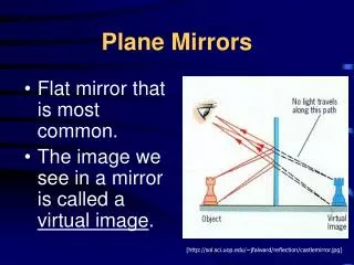
Drawing Ray Diagrams for Plane Mirrors. SNC2D Science. Step 1. image. Draw a line to indicate the mirror Draw the object Pick one extreme on the object and carefully measure the distance from this extreme point to the mirror.

E N D
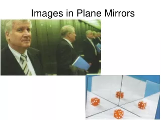
Drawing Ray Diagrams for Plane Mirrors SNC2D Science
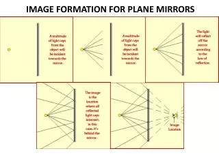
Step 1 image Draw a line to indicate the mirror Draw the object Pick one extreme on the object and carefully measure the distance from this extreme point to the mirror. Mark off the same distance on the opposite side of the mirror and mark the image of this extreme point. Repeat this process for all extremes on the object until you have determined the complete location and shape of the image. observer object
Step 2 Pick one extreme on the image and draw the reflected ray that will travel to the eye of the observer. Draw a bold (solid) line for the reflected ray (from the mirror to the eye) and a dashed line as an extension of this reflected ray; the dashed line extends behind the mirror to the location of the image point. The reflected ray should have an arrowhead upon it to indicate the direction that the light is traveling. The arrowhead should be pointing towards the eye since the light is traveling from the mirror to the eye.
Step 3 Draw the incident ray for light traveling from the corresponding extreme on the object to the mirror. The incident ray reflects at the mirror's surface according to the Law of Reflection… but you don’t need to measure the angles! Why? Since you drew the reflected ray in step 2, the point of incidence has already been determined; the point of incidence is merely the point where the line of sight intersects the mirror's surface. You can merely draw the incident ray from the extreme of the object to the point of incidence on the mirror's surface. Thus draw the incident ray from the extreme point to the point of incidence. Once more, be sure to draw an arrowhead upon the ray to indicate its direction of travel. The arrowhead should be pointing towards the mirror since light travels from the object to the mirror.
Step 4 Repeat steps 2 and 3 for all other extremities on the object. Once repeated for each extreme, your ray diagram is complete.
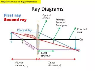
Some points to know: C = Centre of Curvature R = Radius of curvature F = Focal point f = focal length Principal Axis = a line passing through C & F (i.e. through the centre of the sphere) V = Vertex; the geometric centre of the mirror A concave mirror is like a segment of a sphere:
Steps First, Recall the 2 Rules of Reflection for Concave mirrors: Any incident ray traveling parallel to the principal axis on the way to the mirror will pass through the focal point upon reflection. Any incident ray passing through the focal point on the way to the mirror will travel parallel to the principal axis upon reflection.
Step 1 Pick a point on the top of the object and draw two incident rays traveling towards the mirror. Using a ruler, draw one ray so that it passes exactly through the focal point on the way to the mirror. Draw the second ray such that it travels exactly parallel to the principal axis. Mark direction with arrowheads.
Step 2 Time to reflect those rays! The ray that passes through the focal point on the way to the mirror will reflect and travel parallel to the principal axis. Use a ruler to accurately draw its path. The ray that traveled parallel to the principal axis on the way to the mirror will reflect and travel through the focal point. Mark direction with arrowheads. Extend the rays past their point of intersection.
Step 3 Mark the image of the top of the object. The image point of the top of the object is the point where the two reflected rays intersect. Of course, the rest of the object has an image as well and it can be found by applying the same three steps to another chosen point.
Steps Repeat the process for the bottom of the object. Then, SALT your diagram! Size Attitude Location Type For this example, the object was beyond C – the Centre of Curvature of the mirror. So it is: SSmallerAinvertedLBetween C&FT Real
Object beyond C SSmallerAinvertedLBetween C&FT Real
Object at C SSameAinvertedLAt CT Real
Object between C & F SLargerAinvertedLBeyond CT Real
Object between F & Mirror *image appears farther away than object’s distance to mirror SLargerAUprightLFarther away*T Virtual
Object at F No image! Image is ‘at infinity’
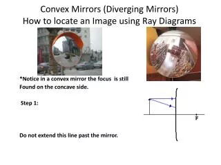
Convex Mirrors A convex mirror is also like a segment of a sphere: If the concave mirrors are like the inner surface of a sphere, then convex ones are like the outer surface of the sphere. This puts F&Cinside the mirror.
Steps There are 2 simple rules of reflection for convex mirrors. These rules represent slight revisions of the two rules given for concave mirrors: Any incident ray traveling parallel to the principal axis on the way to a convex mirror will reflect such that its extensions passes through thefocal point. Any incident ray traveling towards a convex mirror such that its extension passes through the focal point will reflect and travel parallel to principal axis.
Step 1 Pick a point on the top of the object and draw two incident rays traveling towards the mirror. Using a ruler, draw one ray so that it travels towards the focal point on the opposite side of the mirror; this ray will strike the mirror before reaching the focal point; stop the ray at the point of incidence with the mirror. Draw the second ray such that it travels exactly parallel to the principal axis. Place arrowheads upon the rays to indicate their direction of travel.
Step 2 Once these incident rays strike the mirror, reflect them according to the rules of reflection for convex mirrors. The ray that travels towards the focal point will reflect and travel parallel to the principal axis. Use a ruler to draw its path. The ray that traveled parallel to the principal axis on the way to the mirror will reflect & travel in a direction such that its extension passes through the focal point. Align a ruler with the point of incidence and the focal point, and draw the second reflected ray. Place arrowheads upon the rays to indicate their direction of travel. The two rays should be diverging upon reflection.
Step 3 Locate and mark the image of the top of the object. The image point of the top of the object is the point where the two reflected rays intersect. Since the two reflected rays are diverging, they must be extended behind the mirror in order to intersect. Using a ruler, extend each of the rays using dashed lines. Draw the extensions until they intersect. The point of intersection is the image point of the top of the object.
Step 4 Repeat the process for the bottom of the object. At this point the complete image can be filled in. And, now: SALT your diagram! Size Attitude Location Type Image is: Smaller Upright Closer Virtual
Object beyond C SSmallerAUprightLBetween F&VT Virtual
Object at C SSmallerAUprightLBetween F&VT Virtual
Object between C & F SSmallerAUprightLBetween F&VT Virtual
Object between F & Mirror SSmallerAUprightLBetween F&VT Virtual
Object at F SSmallerAUprightLBetween F&VT Virtual
Guess what? There’s Math! Just two teensy, tiny (but useful) equations: Mirror Equation The image distance, di, is negative if the image is virtual (behind or ‘in’ the mirror) Magnification Equation The image height, hi, is negative if the image is inverted compared to the object.
Is this a little difficult? Maybe. You just have to: Know the rules Follow the rules Be as precise as possible
And, in case you can’t follow that: … maybe this is a little more your speed!