Download
1 / 40
400 likes | 690 Views
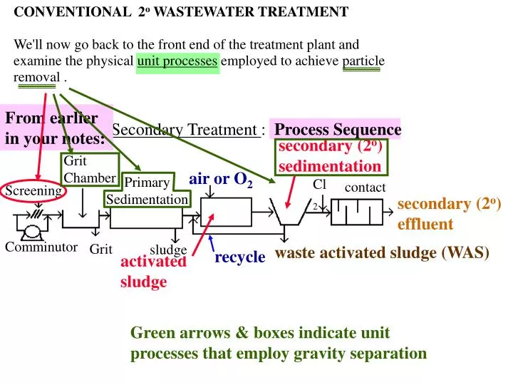
secondary (2 o ) sedimentation. From earlier in your notes:. Secondary Treatment : Process Sequence. recycle. activated sludge. Grit Chamber. air or O 2. Primary Sedimentation. Cl 2. contact. Screening. secondary (2 o ) effluent. Comminutor. Grit. sludge.

E N D
secondary (2o) sedimentation From earlier in your notes: Secondary Treatment : Process Sequence recycle activated sludge Grit Chamber air or O2 Primary Sedimentation Cl2 contact Screening secondary (2o) effluent Comminutor Grit sludge waste activated sludge (WAS) Green arrows & boxes indicate unit processes that employ gravity separation CONVENTIONAL 2o WASTEWATER TREATMENT We'll now go back to the front end of the treatment plant and examine the physical unit processes employed to achieve particle removal .
PARTICLE REMOVAL I. Gross Particle Removal: Accomplished by screening Screening is usually the first process in the treatment of raw wastewater. Screening is accomplished via a device with openings of a uniform size to remove coarse particles. Devices employed can be parallel bars, rods or wires, gratings, mesh, perforated plates, etc. Commonly used are vertical ( perpendicular to flow) or slanted bars spaced with openings of 25 to 75 mm (bar racks). Racks are either manually cleaned (periodic) or mechanically cleaned (periodic or continuous).
If the waste contains a lot of organic material which accumulates on • the screen, it is often passed to a ________________ to grind it up. • These materials are reintroduced to the flow and removed • downstream. • Alternately, materials removed by screening may be disposed of • by burial or incineration. • The channel in which a bar rack is installed is designed to insure a • flow velocity high enough to prevent any sedimentation of grit • (which is removed downstream). i.e., sedimentation is NOT desirable in the channel for the bar rack. comminutor
II. Particle Removal by Gravity Forces The process of removing particles by sedimentation is employed in both water and wastewater treatment. In the course of conventional secondary treatment 3 points can be identified where settling is used. 1. 2. 3. It is useful to look at sedimentation (a Unit Process) to see how it can be modeled or empirically described, and then to use such concepts in design. Grit chambers Primary sedimentation tank (1o clarifier) Secondary sedimentation tank (2o clarifier)
Classes or Types of Sedimentation • Four types may be defined as a function of the solids concentration • in suspension and the tendency of the solids to interact with one • another as they settle. • Class I : Settling • Occurs in settling of dilute suspensions (<500 mg/L) of • particles with little or no interaction. Each particle settles as an • individual entity (No agglomeration or "flocculation" occurs which • would change particle size and settling velocity). No interaction between particles as they settle. Discrete
Discrete settling is the only sedimentation process which can be rigorously modeled. Ex. Sedimentation in a grit chamber may be considered to be discrete, but this is the only solid separation process where Class I sedimentation theory may be successfully applied. Class II Settling Occurs in dilute suspensions (< 500 mg/L) of flocculent particles. Particles coalesce or flocculate during settling so that their mass ____________ and settling velocity ___________ as they fall. increases increases Interaction between particles as they settle. Flocculent
An example of flocculant settling is what happens in the primary • sedimentation tank or in precipitation of chemical flocs (Ex, using • lime to precipitate PO4-3) • Class III. or Settling • Occurs in suspensions of intermediate concentration (500 to • 2000 mg/L). Inter-particle forces hinder settling of neighboring • particles. Particles tend to remain in fixed positions (relatively) • with respect to one another and the mass of particles settles as a • unit. A distinct "solid-liquid interface" develops at the top of the • settling mass with clarified liquid above and the particle mass • below. Particle interaction Zone hindered
An example of this class of settling behavior is the sedimentation of activated sludge in the secondary sedimentation tank. An experiment in Zone settling: As time passes, the solids separate by settling and an interface is observed between the settling solids and the solids-free solution. At time = 0 start with a homogeneous suspension A plot of the height of the interface vs. time yields the Zone Settling Velocity (ZSV), which is what you’d use to do a design. Slope =ZSV height time
Class IV. Settling Particles are sufficiently concentrated that they form a "structure" and settling occurs by compression of the structure (water gets squeezed out) by the weight of additional solids settling from above. Ex., The solids (sludge) in the bottom layer of a secondary sedimentation tank. gel-like Compression
Modeling of Sedimentation • 1. Discrete Settling - this can be satisfactorily modeled based on • fundamental principles • Requirements: - No particle interaction • - quiescent (laminar) flow • Under quiescent flow conditions, discrete particles reach a • terminal settling velocity (___) • VS = • The terminal settling velocity is attained when the downward • force on the particle (__________) is balanced by • upward forces (___________) and • (________________). Buoyant force, FB Fluid drag FD Gravitational force, FG VS f(particle size & density, fluid density & viscosity) At steady state (constant settling velocity): FD + FB = FG gravity fluid drag buoyant forces
Do a force balance (assuming spherical particles) to get this. A dimensionless number that is the ratio of inertial forces on the settling particle relative to viscous forces. where: = particle diameter = particle density = fluid density = gravitational acceleration = drag coefficient, f (Reynolds #) dP rS rl g Cd
For Laminar Flow Cd = • = 24µ/dplVS • where = dynamic viscosity of water • For spherical particles and laminar flow: • Design Considerations For Discrete Settling • Consider a simplified version of a clarifier. 24/Re So, Re = dplVS/ Substitute into the equation on the previous page to get: Cd m Stoke’s Law VS =
Assume: 1. quiescent conditions in the settling zone 2. steady flow - no hydraulic fluctuations: Q = 3. uniform particle distribution at the clarifier inlet 4. "hit and stick", particles which settle to the bottom (sludge zone) are removed. No particle scour. Parameters: = volume flow rate = surface area of the ideal settling zone = depth of the ideal settling zone = volume of the ideal settling zone (i.e., same concentration, top to bottom) Laminar flow constant Q A hO V
Schematic of our ideal rectangular clarifier: • Modeling of the ideal zone: • Consider a particle which enters the sedimentation unit at the • very top of the water column (remember particles are assumed to • be uniformly distributed with depth). This particle will be removed • if the fluid residence time in the ideal zone is long enough for it to • settle and hit the bottom of the tank (the sludge zone). Q Q hO Uniform particle distribution volume = V Turbulence is permitted @ inlet and outlet (hit & stick) Continuous withdrawal of sludge (no build up) A = surface area Outlet Zone Inlet Zone Ideal discrete Settling zone Sludge Zone
= V/Q The residence time of fluid in the tank is ________________. The maximum distance (vertical) the particle needs to travel is _______________________. The particle will be removed if its settling velocity (VS) is > ________________ . This particle (with VS = hOQ/V) will just make it to the sludge zone. Define this velocity as the ______________ ______________ (VC). hO hO/(V/Q) critical velocity
If all particles coming into the ideal zone have VS > VC we • will remove _________ % of them. • Note that the volume of the ideal zone V = • so VC = hO/(V/Q) = = • the critical velocity of a tank is its flow rate divided by its • surface area. Note: we get partial removal of some particles with VS< VC, if they enter the tank below the top of the water column. VS < VC VS > VC V/Q = surface area of ideal settling zone 100 Q/A A = surface area Uniform distribution of particles over depth trajectory of particle with VS= VC = hO/(V/Q) sludge zone hOA hOQ/hOA
The term Q/A is referred to as the _____________ _____________ or the _____________ _______________ __________________ and is the major design variable for sedimentation tanks (Q/A is just an embodiment of VC). In theory, all you have to do is dimension the tank such that (Q/A) < VS and you'll get 100% removal. Note that for a given flow rate (Q) just need (theoretically) to have some surface area (A) and removal is predicted to be independent of depth !! over flow rate hOQ/hOA VC = hO/(V/Q) = surface loading rate
We can save a lot of money and make the tank real shallow-RIGHT? • Problems with shallow depths: • - For a given Q and AS, as hO _____, horizontal velocity ____ • greater likelihood for particle scour ("hit and stick" • assumption breaks down). • - with shallow depths wind mixing can produce turbulence • which reaches to the tank bottom and causes particle scour. • - need room for sludge removal devices (scrapers, etc.). NO!
Removal of Particles with VS < VC If VS < VC is there any removal? Why or Why not? There is some removal of particles with Vs< VC because particles are uniformly distributed over the depth of the clarifier. Those which enter @ heights < hO do not have to fall so far and may be removed. For particles with VS1= h1/(V/Q) < VC , have _________ % removal for those which enter the reactor at height < h1. Have __________% removal for those which enter at height > h1. YES! Same conc. top to bottom @ inlet hO h1 height 100 0
Since the particle concentration is uniform over depth, the overall • fraction (removed) of particles with VS = VS1 is: = • In a typical wastewater suspension, one finds a continuum of • particle sizes and, therefore, a continuum of VS values. • The spectrum of particles settling velocities can be determined by: • 1. sieve analysis and density measurements • i.e., given S and dP, the Stokes settling velocity can be • calculated for each size fraction. • 2. From a settling column (more on this in a minute). a lab test. So the fractional removal of a slow settling particle is the ratio of its settling velocity to the critical velocity.
As VS, then the fraction (f) with settling velocity < VS until all particles are accounted for. Ro In either case the data may be used to construct a velocity distribution curve. We can use this curve to calculate the overall removal efficiency for a given design. 1.0 Fraction (f) of particles with velocity < VS VS
Example: If the overflow rate = Q/AS = VC then: • 1. We know we will have 100% removal of particles with • VS > VC . Let the fraction of particles with velocity • < VC = fC (from the graph) • the fraction with VS > VC = _____________________ • and will be 100% removed. (1-fC) = fraction of particles that will be completely removed. fC 1.0 Fraction of particles with velocity < VS f VC VS 1 - fC
1.0 This term is just the area under the hatched part of the curve. fC Df VS' Fraction of particles with velocity < VS f VC VS 2. For some incremental fraction of particles f with a an average settling velocity VS' < VC we will have a fractional removal of : __________________ the total amount removed will be: ______________ For "n" incremental fractions the amount removed will be: or, in differential form, for all particles with VS < VC the amount removed is: VS'/VC Df(VS'/VC)
3. The total (overall) fractional removal is the sum of the • removal of particles with VS > VC and particles with • VS < VC • Overall fraction removed = Ro = This term accounts for 100% removal of particles with VS > VC This term accounts for fractional removal of particles with VS < VC 1 - fC +
Determination of VSvs. f distribution by settling column 1. Set up a column with a sampling port at some depth = z. Start with a uniform suspension of particles with an initial suspended solids concentration = CO. CO = wt./volume (or use turbidity) Data Analysis: At some time = ti, all particles with a settling velocity > z/ti will be completely removed. However, all particles with VS < z/ti will be present in their original concentration! I.E., each particle of this type which falls below depth = z is replaced from above. 2. At various times (t) withdraw samples and measure the suspended solids concentration C(t) z C = CO @ time = 0 sampling port
Illustration: • So, if Ci = concentration measured @ time = ti , then the fraction (f) • of particles with VS < z/ti = __________________. • have all necessary data to construct f vs. VS plot. 1.0 Fraction (f) of particles with velocity < VS = Ci/Co f VS= z/ti z o o o time y y t = 0, uniform suspension t = ti, complete removal of particle type x, particle type y and o still present in original concentration at depth = z Ci/Co
Flocculent Settling(Class II) Primary settling serves as a good example. Particles contact one another and coalesce as they settle so that their settling velocity increases. Particle contact is caused by: a. _______________________ sedimentation: large fast-settling particles overtake smaller slow-settling ones, and they stick together. differential
b. hydraulic disturbances (fluid shear) • c. brownian motion • Particles continue to grow in size as they settle until they: • a. hit bottom • b. get so big that fluid shear breaks them up. • Typical particle trajectory in flocculent settling: gradient of fluid velocities flocculent discrete sedimentation depth hO time
In flocculent settling particle removal efficiency is governed by: a. b. c. There is no suitable mathematical model to predict the effect of flocculation on sedimentation. Process design is commonly based on laboratory tests. The Quiescent Settling Test: Performed in a large column. Column depth should be greater than the expected design depth for the sedimentation tank. Column diameter must be large enough to make "wall effects" negligible (typically 6" or 15 cm) Overflow rate (Q/A) Depth, hO (greater chance for aggregation if deeper) Concentration and type of particles
Rosample = % removal = ( )100 Test: h1 Sampling ports at known depths 1. initially start with uniform mixture of the test suspension @ time = 0 2. let settle and sample each port at time intervals 3. Measure the concentration in each sample and calculate the % removal of solids as: h2 h3 h4
4. Plot Rosample on an h(depth) vs. time grid 5. Draw contours on the plot for equal % removal (isoconcentration lines) And this point would be on the line for 80% removal. 68 72 85 50 56 66 By interpolation, these points would be on the 70% isoconcentration line. And these would be points on the line for 60% removal 80% 60% 40% 20% h1 h2 h3 h4 h5 time 100% 0 [see pp 120-123 in Environmental Engineering by Peavy et al.] depth time
6. For any tank depth, hO, and hydraulic retention time, • = V/Q, the total % removal may be determined as follows: • Suppose hO and are as shown above. [Note VC = ] • Then Rob = 40% of the particles had settling velocities VS > VC • and are completely removed. Of the remaining (100% - Rob = 60%) • particles, the fraction (Roc - Rob = 20%) have an average settling • velocity of VS = ____. So the fraction VS/VC =________ • will be removed. Continue in this manner to find the • total % removed (Rototal) as: V/Q 0 100% hc hb depth ha hO time hO/q = Q/A ha/q (ha/q)/(hO/q) = ha/ hO
0 100% hc hb depth ha hO time 40% 20% 20% 20% Note: Rototal is f( and hO) and also f(CO) the initial T.S.S. concentration for the test.
Alternate Calculation Procedure: • Finally, an additional (60+40)/2 = 50% were removed in depth • increment h3. Add up each of these % removals and normalize • each to the fraction of the total depth which it represents (i.e., the • fraction h1/hO = fraction of depth with ________% removal of • particles). Look at particle removal (%) over the depth hO. See that an average of were removed in depth increment of h1 An additional 100 % depth 40% 80% 60% 20% were removed in depth increment h2 90
Rototal = For this example Rototal is still f(hO, , type and concentration of particles). Either approach should give you the same answer.
These calculations can be repeated for different • surface loading rates (Q/AS values) • or depths to produce a family of curves. Increasing hO Increasing Q/AS RO RO hO Q/AS
Primary Sedimentation Units in Wastewater Treatment Objective: removal of settleable organic particles (subsequent to grit removal) Design Parameters: depth and overflow rate - in absence of quiescent settling test use: hO = 2 to 5 meters Q/AS = 25 to 40 m3/day-m2 Configurations: A. Rectangular scum trough & rotary skimmer baffle skimmer outlet weirs influent Q Q effluent L = 15 to 90 m q = 1 to 3 hrs L/W = 3:1 to 5:1 W is dictated by available sludge collector dimensions endless belt sludge withdrawal scraper 1% slope sludge hopper
B. Circular: can have various configurations • Ex., center feed vs. peripheral feed Influent (center feed) baffle effluent Scraper 1 12 Sludge withdrawal
Often take design values (such as surface area) and apply a "scale up" factor of 1.25 to 1.75 x Ex., Adesign = 1.5 Atest This accounts for "non-ideal" field conditions such as: 1. 2. 3. 4. 5. 6. variable solids conc. and variable nature of solids Typical removals in primary sedimentation tanks: % removal of BOD520 C _____, % removal of T.S.S turbulence wind-driven currents or currents from density differences dead zones ( regions of reactor with stagnant fluid) bottom scour hydraulic fluctuations (Q constant) 50-60 25-40