Download
1 / 21
210 likes | 406 Views
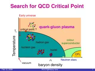
An EBIS-based RHIC Preinjector. RHIC EBIS design. A. Pikin. Preinjector Group Collider-Accelerator Department. Project parameters of RHIC EBIS (I el =10A):. Number of extracted ions of Au 32+ (ions per pulse): 3.4 x10 9 Total extracted ion charge (elem. charges per pulse ): 5.5x10 11

E N D
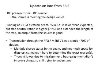
An EBIS-based RHIC Preinjector RHIC EBIS design A. Pikin Preinjector Group Collider-Accelerator Department
Project parameters of RHIC EBIS (Iel=10A): • Number of extracted ions of Au32+ (ions per pulse):3.4 x10⁹ • Total extracted ion charge (elem. charges per pulse ): 5.5x10¹¹ • Capacity of ion trap (elem. charges): 1.1x10¹² • Extraction time: 10-40 μs • Electron beam current: 10 A • Electron beam current density in ion trap: 575 A/cm2 • Electron energy in ion trap: 20 keV • Length of ion trap: 1.5 m • Magnet field in the center of SC solenoid: 6 T • Maximum rep. rate 5 Hz The primary difference in the RHIC EBIS, compared to our Test EBIS, is the doubling of the trap length to increase the ion output. Other new features we plan to incorporate into the final EBIS will be made in order to make the final EBIS more robust.
Electron Beam • The existing 10 A electron gun with IrCe cathode meets the RHIC EBIS requirements, with an estimated lifetime of >20,000 hours. • The present cathode is actually capable of operating at 20 A with lifetime of 3000-5000 hours. • In order to have a reserve for a possible future increase of the ion beam intensity, we are building the electron gun electrodes and collector with the capability of operating at 20 A.
Current density of cathodes versus temperature (G. Kuznetsov, Journal of Physics (Japan): Conference Series 2 (2004) 35–41) Gun lifetime with LaB 6 and Ir-based cathodes (G. Kuznetsov, NIM in Physics Research A 340 (1994) 204-208) Evaporation rates of some materials versus current density. (G. Kuznetsov, NIM in Physics Research A 340 (1994) 204-208)
Electron gun • Method of forming the electron beam – the same as in existing electron gun: magnetic compression of the beam generated by a cathode immersed in a magnetic field. • Perveance: P=2.5x10⁻⁶ A/V3/2(2 times higher than we have now, to allow operation at reduced voltage) with bell-shaped radial current emission profile • Electron current Iel. max=20 A at Uanode=40 kV • Magnet field on the cathode: Bcathode=(0.18-0.2) T • Cathode material: IrCe • Maximum emission current density J=30 A/cm2 for life time 3-5 thousand hours. • Cathode diameter: 9.2 mm, • Convex shape, Rsphere=10-12 mm,
Design of the electron gun Replaceable gun unit Electron gun
Simulations of the electron beam transmission from the electron gun. Iel=20.5 A, Ua=38.5 kV
Simulation of the electron beam generation from the electron gun Bell-shaped radial distribution of the emission current density from the cathode is produced to distribute the power load on the EC more evenly.
Electron current and ion intensity scaling With optimum perveance of the electron beam in a trap of our EBIS Ptrap=3.54x10⁻⁶ A/V3/2and the length of the trap ltrap=1.5 m the capacity Q of the the ion trap (space charge of electrons within the ion trap boundaries) depends on the electron current I elas: With electron current up to Iel=10 A the number of extracted ions can be determined by the formula: Scaling EBIS to I el=20 A, for Kneutral=0.5 and Kspectrum =0.2, we can expect the intensity of ions Au32+ to increase from 3.4x10⁹ to 5.5x10⁹per pulse. (60% increase) Kneutral – coefficient of neutralization of the electron beam space charge by ions Kspectrum – fraction of ions with charge state Zion in the ion spectrum
Electron collector (assembly) • Designed to dissipate Pel= 300 kW peak power • More uniform distribution of • e-beam • Increased surface area • (2300 cm2) • Calculated max power density on EC surface (for 300 kW): • pmax= 485 W/cm2 • Outer surface of collector is at atmosphere (~ no internal cooling lines). • Cooling channels: ID 9 mm in a cylinder 15 mm thick, 10 parallel loops, each consisting of 6 individual channels connected in series. • Cooling water: pressure P=20 bar, flow= 4 GPM per loop (40 GPM total). • Calculated critical heat flux is CHF=790 W/cm2 (Biasi) or CHF=1290 W/cm2 (Bowring). With expected max. power density 485 W/cm2 we have a comfortable safety factor of 2 or more. Pressure rise increases CHF because the boiling temperature increases.
Optical simulations of the electron collector (Iel=20 A) Eel=11.5 keV Eel=15 keV Simulations of the 20A electron beam transmission in EC Electron beam power density distribution on EC surface
ANSYS simulations of electron collector for Iel=20A, Eel=15 keV, 50 ms ON, 50 ms OFF ANSYS simulation of temperature distribution in EC at peak power. 20 A, 15 kV, 50% DC Von Mises stress distribution at peak power Time dynamics of the average temperature in a hottest spot with 50% duty cycle (20 A, 15 kV) Distribution of power density flux in EC at the end of 50 ms electron beam pulse
ANSYS simulations of electron collector for Iel=20A, Eel=15 keV, 30 ms ON, 170 ms OFF Distribution of Temperature cycling in a hottest node of EC in equilibrium of average temperature Temperature distribution on EC cylindrical surface at the end of 30 ms electron beam pulse
Results of simulations RHIC EBIS electron collector was designed and simulated for 300 kW electron beam power. After analysis of several EC material we selected Brush Wellman copper-beryllium alloy Hycon-3, because it has the largest margin between the yield stress and the resulting stress. ANSYS stress simulations demonstrate, that for 50% duty cycle (50 ms ON, 50 ms OFF) and 15% duty cycle (30 ms ON and 170 ms OFF) the average values of stresses and their amplitudes provide life time before fatigue failure well over 108 cycles.
Vacuum • Pressure requirement in the ionization region P=(1-3)x10-10 Torr • Approaches(incorporated on the Test EBIS): • Use of traditional UHV technology including preliminary vacuum firing at 9000C. • Separating central chamber from the heavily outgasing regions of electron gun and collector with low conductance paths. • Plus: • Increase ID of the central chamber from 4” to 6” for better pumping on sides and allow for placing strips with NEG (Non-Evaporable Getters) materials inside the central chamber. • Have one more stage of vacuum separation between EC and ionization region. • Making the electron gun unit replaceable without breaking vacuum in the rest of EBIS.
Superconducting solenoid (SCS) • Length of the SCS coil: 200 cm • Magnet field: 6 T(Required to provide the same magnet compression of a 20 A electron beam as a 10 A beam, relieving power load on electron collector, providing condition for generating higher ion charge states if needed, increasing magnet field in a drift space outside the SCS) • ID of the warm bore: 204 mm (8”)(vacuum conductance from the center of the ionization region is increased 1.7 times compare with existing EBIS chamber, more room for HV leads) • Supplemental helium recondenser to eliminate time consuming He refilling during run. • Investigating the possibility of making the SCS in the BNL magnet group
External ion sources • Requirement: ion sources capable of producing various ions, including Au for RHIC and other ion species (gases and solids) for NSRL applications. • LEVA: Available ion source, tested for ion injection. • Hollow cathode ion source: studied, upgraded, ready to be tested for ion injection: Iion= 15.6 µA (Cu, 14kV), RMS emittance at 14 kV is ε=29π·mm·mrad) • Also we are considering use of CHORDIS plasma ion source with versatile options for metals injection.
Conclusion: • We have a detailed design of most components of EBIS, satisfying the RHIC requirements. • The design provides high reliability and easy maintainability. • The ability exists to increase the ion beam intensity up to 60% by upgrading EBIS to electron current 20 A.