Download
1 / 13
130 likes | 329 Views
T-CARRIERS. Thought For The Week No Question Is A Bad Question!. Key Point. T-Carriers Are A Primary Means Of Point-To-Point Network Connectivity. LESSON OBJECTIVES. T-carriers Have Existed In The Telecommunications Industry For Quite Some Time.

E N D
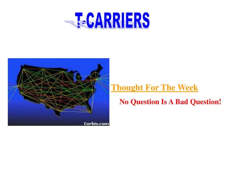
T-CARRIERS Thought For The Week No Question Is A Bad Question!
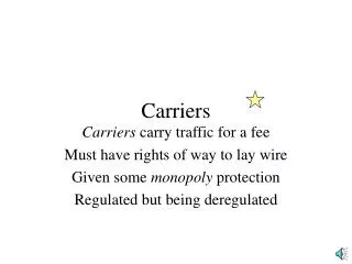
Key Point T-Carriers Are A Primary Means Of Point-To-Point Network Connectivity.
LESSON OBJECTIVES T-carriers Have Existed In The Telecommunications Industry For Quite Some Time. • At The End Of Lesson 4, You Should Be Able To: • Describe The Differences Between T1, FT1, • And Digital Signal Level 3 (DS3) Systems • List Applications That Use T1, FT1, And DS3 • Technologies
Digitizing Voice • Digital Voice Transmission Offers Several • Advantages: • Digital Signals Are Less Susceptible To • Interference; It Is Easier To Distinguish Noise • From Signal. • Binary Patterns Can Be Reproduced Exactly, • And “Cleaned Up,” When They Pass Through • Switches, Multiplexers (Muxs), Or Repeaters. • Digital Voice Signals Can Be Multiplexed With • Other Digital Data.
T-Carriers • T-carrier Rates Are Shown In The T-Carrier • Rates Table. Number of Voice Circuits Standard Line Type Bit Rate DS0 DS1 DS1C DS2 DS3 DS4 N/A T1 T1C/D T2 T3 T4 1 24 48 96 672 4032 64 Kbps 1.544 Mbps 3.152 Mbps 6.312 Mbps 44.736 Mbps 274.176 Mbps North America
T-Carriers Number of Voice Circuits Standard Line Type Bit Rate E1 E2 E3 E4 E5 M1 M2 M3 M4 M5 30 120 480 1920 7680 2.048 Mbps 8.448 Mbps 34.368 Mbps 139.264 Mbps 565.148 Mbps Europe
T-Carriers Number of Voice Circuits Standard Line Type Bit Rate 1 2 3 4 5 6 F-1 F-6M F-32M F-100M F-400M F-4.6G 24 96 480 1440 5760 23040 1.544 Mbps 6.312 Mbps 34.064 Mbps 97.728 Mbps 397.20 Mbps 1588.80 Mbps Japan
T1 • T1 Circuits Are Dedicated Services • Connecting Networks Or LANs Over • Extended Distances. • The Sample T1 Configuration Diagram Presents a Typical Configuration. Sample T1 Configuration
T1 • As With A DDS Circuit, We Lease A T1 Circuit • Between Two Locations. • The DS-0 Network Diagram Demonstrates This By Showing A Typical Four-Office Telephone Network Built Using Individual DS-0 Lines. DS-0 Network
T1 • The T1 Network Diagram Demonstrates A Way • To Consolidate Interoffice Communications Into A • Single Backbone Consisting Of Four T1 Lines, • Capable Of Meeting Changing Traffic Demands • On The Fly. T1 Network
T1 • The T1 WAN Diagram Illustrates A Typical T1- • Based WAN. T1 WAN
T3 And North American Digital Hierarchy • The North American Digital Hierarchy Is Created • Using A Series Of TDMs As Shown On The North • American Digital Hierarchy Diagram. North American Digital Hierarchy
Circuit Costs • Lower T1 Circuit Costs Are Enabling More • And More Companies To Carry Bandwidth- • Intensive Applications.