Download
1 / 27
350 likes | 1.27k Views
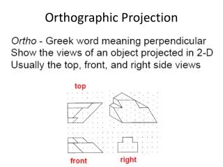
Orthographic Projection. Ortho -- perpendicular The system of drawing views of an object by projecting points perpendicularly onto projection planes. Projection lines represent line of sight Line of sight perpendicular to projection plane Multiviews

E N D
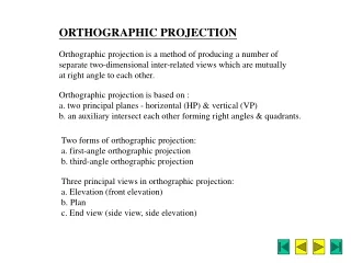
Orthographic Projection • Ortho -- perpendicular • The system of drawing views of an object by projecting points perpendicularly onto projection planes. • Projection lines represent line of sight • Line of sight perpendicular to projection plane • Multiviews • two-dimensional views of an object projected upon two or more planes of projection using orthographic projection techniques.
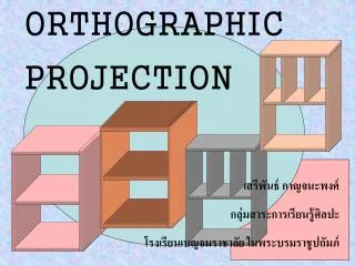
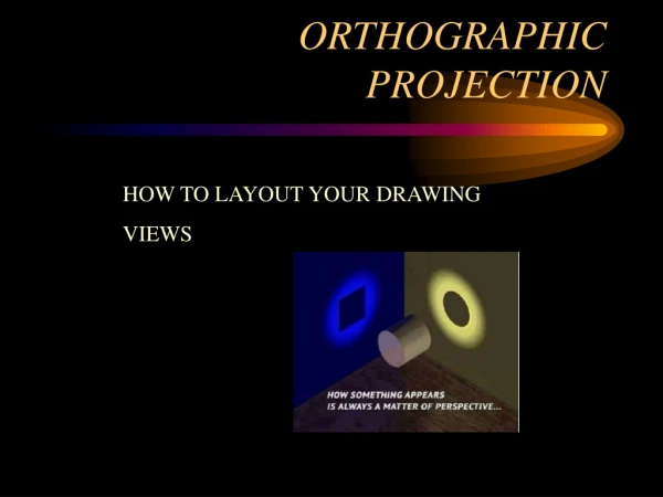
Glass Box Model • Place object in a glass box so the sides of the glass box are parallel to major surfaces of the object. • Third-Angle projection - used in the US: • Top view directly above the front view • Right-side view to the right of front view • Faces of the glass box serve as planes of projection • Cut glass box along edges and unfold to obtain multiviews
Orthographic Views • Common projection planes (aka principal projection planes) • frontal F front view • horizontal H top view • profile P right-side view • Cut and open the glass box to get principal orthographic views • Other views: • bottom, rear, left-side
Dimensions • Dimensions necessary to define object: • Height H -- FV & RV • Width -- TV & FV • Depth -- TV & RV • Alignment of views • align corresponding dimensions • Represent hidden edges by dashed lines
Selecting the Front View • Represents the most natural position of use • Provides the best shape description or most characteristic contours • Has longest dimension • Has fewest hidden features
Object suspended in a glass box, producing the six principal views
Types of Lines • Object lines (visible lines) • solid lines • represent visible surfaces or edges of the object • Hidden lines • dashed lines • invisible edges of the object • Centerlines • long-short dashes • used to show centers of circles and arcs • Others: extension, dimension, phantom, section, cutting-plane
Line Precedence • When one type of line falls in line with a different line type, draw the line that is most important based on precedence: • Object lines take precedence over hidden lines and centerlines. • Hidden lines take precedence over centerlines. • In sectioning, cutting plane lines take precedence over center lines.
Representing Planes • Normal Plane • parallel to a principal projection plane • can be seen in only one view as True Size • Inclined Plane • tilted with respect to two principal proj planes • seen in two views; not true size • Oblique Plane • tilted with respect to all principal proj planes • seen in three views; not true size
Numbering the isometric pictorial and the multiviews to help visualize an object
Orthographic Views in AutoCAD • Group entities together into LAYERS. Use the layer manager to create layers. • Object lines • hidden lines • section lines and hatching • text and dimensions • title border • Create rectangles for front, top, and right-side views • use 3rd angle projection • appropriate spacing between views
OV with AutoCAD • Use horizontal construction lines to locate height dimensions common between FV and RV. • Use vertical construction lines for width dimensions in FV and TV. • Use a 45-degree projection line (miter line) to transfer depth dimensions between TV and RV. • Locate and plot projections of normal planes first, then inclined and oblique planes. Use solid lines for all visible object lines.
OV with AutoCAD • Locate all hidden edges; use dashed lines. • Locate centerlines of all circles and arcs. • Check visibility of lines following precedence rules. • Add dimensions and text. • Import title block.