Download
1 / 141
1.63k likes | 2.44k Views
Solid State Electronics. Field Effect Transistors Ronan Farrell. Recommended Book: Streetman, Chapter 6 Solid State Electronic Devices. Solid State Electronics. Topics we’ll be covering JFETs, MESFETs, MOSFETs and IGFETs. Qualitative explanation of the operation of the MOSFET

E N D
Solid State Electronics Field Effect Transistors Ronan Farrell Recommended Book: Streetman, Chapter 6 Solid State Electronic Devices JFETs/MOSFETs
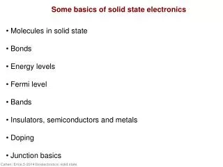
Solid State Electronics Topics we’ll be covering • JFETs, MESFETs, MOSFETs and IGFETs. • Qualitative explanation of the operation of the MOSFET • Fabrication of MOSFET, depletion or enhancement • MOSFET equations and models. • Small signal model and parasitic correspondence. • Imperfections such as short channel effects, hot electron effect , latch-up • Sub threshold operation, punch-through, pinch-off JFETs/MOSFETs
History Historically, field-effect transistors (FETs) were proposed prior to bi-polar transistors, in 1925 by Lilienfeld. In particular MOSFETs were the first type of transistor to be ever suggested. What actually happened is that the manufacturing technology was not good enough at the time to make a FET and Bardeen and Brattain (Bell Labs) made the first BJT using Germanium when trying to make a FET by trying almost everything they could think off. Shockley (Bell Labs) understood what happened and suggested an improved design. Thus entered the age of the BJT (1950). It took to 1960 to make the first MOSFET (Kahng and Atalla, Bell Labs). Since then Silicon MOSFETs have gradually replaced BJTs in most applications. JFETs/MOSFETs
History For interest, Schockley left Bell Labs to set up his own company, Schockley Semiconductors in California, near San Francisco. His company had the best engineers going but he had a pet project, 4 layer diodes which dominated the direction of the company. Eight of his best engineers left because of Schockley’s personality and set up Fairchild Semiconductor, to concentrate on transistors. Later two more left to set up Intel. Intel was the first company to make MOS RAM, a 1K chip in 1970’s. Fairchild is currently worth USD 2 Billion and Intel is worth USD 168 Billion. This was the start of Silicon Valley. Schockley’s company went bankrupt, he ended up lecturing where after some racial comments on intelligence and genetics, he lost that too. Basically he ended up penniless and disgraced. JFETs/MOSFETs
JFETs, MESFETs, MOSFETs and IGFETs • JFET • Junction Field Effect Transistor • MESFET • Metal-Semiconductor Field Effect Transistor • MOSFET • Metal-Oxide-Semiconductor Field Effect Transistor • IGFET • Insulated Gate Field Effect Transistor • MISFET • Metal-Insulator-Semiconductor Field Effect Transistor JFETs/MOSFETs
FETs and BJTs In PN junctions we had minority and majority current carriers on both P side and N side of the junction. In FETs only the majority carriers are used. For this reason FETs are often called Unipolar Transitors. The current in a FET does not cross any PN junction. In BJTs, there are two PN junctions and current is carried by both minority and majority carriers and hence are called Bipolar Transistors, hence the B in BJT. JFETs/MOSFETs
JFET In very simple terms the JFET can be considered as a sandwich of 3 layers, the top and bottom being one type with the centre the other type. The top and bottom layers are connected together and are called the GATE of the transistor. The current flows through the centre layer JFETs/MOSFETs
JFET As can be seen from the diagram, there is actually no difference between the left and right hand side of a FET in theory. Therefore we can call either side DRAIN or SOURCE. It’s more common to say that current flows from DRAIN to SOURCE. The names come from electron flow directions, the SOURCE to DRAIN is the direction of electron flow In practice there are some minor manufacturing issues. JFETs/MOSFETs
JFET The JFET operation is dependent on the variation of the depletion region. The depletion region is defined as being a region where all the carriers have been depleted due to recombination at the junction. Thus normally current would flow through a depletion region unless it was diffusing across the junction. You can imagine the depletion region as an insulator. JFETs/MOSFETs
JFET However the depletion region width is dependent on the bias voltage. If we make the depletion region bigger then the conducting centre of the sandwich gets smaller, looks more resistive, carries less current. If we make it smaller, the conductive region increases, carries more current. JFETs/MOSFETs
JFET So to make a JFET work, • Set the gate source voltage to reverse bias the junction. This prevents current flowing into gate, a reversed bias diode. • Changing this reverse bias voltage changes the depletion width. • Changing the depletion width changes the resistance of the conducting channel • Increase it too much and you can close the channel off. JFETs/MOSFETs
JFET The conducting channel of the JFET is normal semiconductor bulk material. However conducting semiconductors are very resistive. This resistance we can calculate, from earlier, from mobilities and doping. However if current flows there’ll be a voltage drop across transistor. This has an effect on the depletion region width. JFETs/MOSFETs
JFET The drain is the current input to the device, therefore at the drain there is no voltage drop compared to drain voltage. At the source, the current has passed through the channel and the source voltage is now the drain voltage less the current * channel resistance VS = VD - IfetRfet JFETs/MOSFETs
JFET Thus there is a gradient in the voltage across the transistor. This means that between the channel (say N type) and the gate (P type) there is a varying voltage. This means that the depletion layer will vary across the junction, thicker at the drain than the source. Remember the drain needs to be at a positive voltage to the gate for reverse bias. JFETs/MOSFETs
JFET - Pinch-Off Now it’s quite easy to see that if there is sufficient reverse voltage across the junction then the depletion layer will close of the channel. This is called pinch-off. For a given voltage, if you drive sufficient current, ie increase the drain voltage sufficiently, you can force the channel close. At this point you can’t drive any more current through the system, it levels off. Any more current would cut the channel, current begin to drop but then current would flow again… equilibrium position is just at pinch-off. JFETs/MOSFETs
JFET - Pinch-Off JFETs/MOSFETs
JFET - Pinch-Off JFETs/MOSFETs
JFET - Pinch-Off Now we know from before that the width of the depletion region is We also said that if we heavily dope one side of the junction compared to the other then effectively all the depletion region is the side of least doping. For good conductivity in the gate, to make it metal-like, we heavily dope the gate and so we can assume all the depletion region is in the centre channel. JFETs/MOSFETs
JFET - Pinch-Off Now we know from before that the width of the depletion region is N type channel We also said that if we heavily dope one side of the junction compared to the other then effectively all the depletion region is the side of least doping. For good conductivity in the gate, to make it metal-like, we heavily dope the gate and so we can assume all the depletion region is in the centre channel. JFETs/MOSFETs
JFET - Pinch-Off Now pinch-off occurs when the depletion width is half that of the channel width. There are two junctions, on each side of the channel. So defining the channel width to be “T”, so JFETs/MOSFETs
JFET - Channel Current We won’t work out the current equation. It is messy mathematically but not difficult. The steps are as follows • The current at all points in the channel must be equal. • In any part of the channel the resistance of that part can be calculated by the width of the available channel and the conductivity. The resistance goes up as the channel narrows. • So you can set the current to be a function of the rate of change of depletion width which is dependent on the current and resistance. JFETs/MOSFETs
MOSFET /IGFET This is probably the most widely used transistor. It is formed by a three layer sandwich. • The top layer is either metal or very heavily doped semiconductor. • The middle layer is an oxide, SiO2. This is a very good insulator. • The third layer is the bulk of the transistor and it is this bulk material that states whether it is N or P type. On either side of the bulk of the MOSFET there are two contact regions, opposite type to the bulk and these form the DRAIN and SOURCE. JFETs/MOSFETs
MOSFET /IGFET Lightly Doped (Substrate) JFETs/MOSFETs
MOSFET The MOSFET device operates by generating (or inhibiting) a conductive layer between the source and drain. In an enhancement MOSFET, the most common type, a channel is formed by the collection of suitable charge carriers just below the gate. This comes from the gate and the bulk material appearing similar to a capacitor. In depletion MOSFETs, a channel naturally exists between the the source and drain but with sufficient reverse bias voltage, a sufficient collection of opposite charge carriers can form and this disrupts the channel JFETs/MOSFETs
MOSFET For the rest of this discussion, only enhancement MOSFETs will be considered. As there is an insulator between the gate and the channel, a later of SiO2, there is NO conductive path between the gate and either the drain or source. Any path that does exist will develop from parasitic capacitors and are only an issue for high frequency operation. There is no DC path though these capacitors can be charged up and this is a difficulty with discrete components. JFETs/MOSFETs
MOSFET The main function of the MOSFET is effectively that of a capacitor. In a JFET, the reverse bias voltage was such that a depletion region was created. No free carriers exist close to the junction because there is both diffusion and drift current across the junction. In the MOSFET with the insulating layer there is no current and hence no depletion region. However the charge on the gate attracts carriers of the opposite sign to the region just under the channel. The greatest concentration of these lie closest to the gate. JFETs/MOSFETs
MOSFET If sufficient number of free carriers are available it is possible to overcome the lightly doped bulk material and change the material type, ie P type to N type. If this occurs and forms a suitable channel between drain and source then current will flow. The width of the channel is dependent on the gate bulk voltage. However as in JFET current flow in bulk semiconductor is resistive and the voltage will drop across it, changing the width of the channel. Hence pinch-off can occur in MOSFETs as well. JFETs/MOSFETs
MOSFET JFETs/MOSFETs
MOS Capacitors As the MOSFET is in many ways just a capacitor we’ll spend some time investigating MOS capacitors and the voltage required to create a region of inversion in the bulk material. JFETs/MOSFETs
MOS Capacitors Equilibrium P Accumulation (negative voltage) P Depletion (positive voltage) P Inversion (large positive voltage) P JFETs/MOSFETs
MOS Capacitors A material’s work function is a measure of the energy required to move an electron from a material to outside of it. qM = Energy required to move electron from metal’s Fermi Level to insulators conduction band. Metals conduction band and valence band are the same JFETs/MOSFETs
MOS Capacitors qS = Energy required to move electron from semiconductor Fermi-Level to insulator’s conduction band. qF = Energy required to move electron from semiconductor Fermi-Level to the semiconductors intrinsic Fermi energy level. JFETs/MOSFETs
MOS Capacitors - - - - - - + ++ +++ + ++ ++ - - - - - Consider a normal capacitor, if we place a positive charge on one side of then negative charge accumulates on the other side. In the MOS capacitor, the same happens. We charge up one side of the plate (ie the gate) to some voltage, and this accumulates the opposite charge in the bulk semiconductor. JFETs/MOSFETs
MOS Capacitors Now let’s assume that we have P type semiconductor and place a negative voltage on the metal. If we do this then we pull additional holes to the surface of the semiconductor near the insulator. But the hole concentration in a semiconductor is defined by the following equation NOTE: Ei defined as halfway between conduction and valence bands. JFETs/MOSFETs
MOS Capacitors In equilibrium in our MOS junction, the Fermi Energy level on both sides would be equal, however the bias applied across the junction will shift it. Apart from this bias, EF will remain constant in the material. So if po increases, and pi and EF, then something has to change, and it’s Ei. Changes in this value indicates that the behaviour of the material is changing. JFETs/MOSFETs
MOS Capacitors If Ei is moving then the position of the conduction and valence also move with it. Basically, for our example, if more hole carriers are available, then the probably of free electron carriers decreases. So graphically, the conduction band goes up, indicating the higher energy required for a free electron carrier. Similarly for the valence band. When the number of dominant free carriers increases due to the MOS capacitance effect, the effect is called ACCUMULATION JFETs/MOSFETs
MOS Capacitors Now imagine we place a positive charge on the metal gate. This would mean the in the P-type semiconductor negative charge would be attracted to the surface of the semiconductor. From before, we can predict that this will force the energy bands in the opposite direction from before, the conduction band dipping lower near the edge of the semiconductor. When the number of dominant free carriers decreases due to the MOS capacitance effect, the effect is called DEPLETION. JFETs/MOSFETs
MOS Capacitors JFETs/MOSFETs
MOS Capacitors If a sufficiently positive voltage is applied then the conduction band can drop below the Fermi Energy Level of the material. Now if we look at the following equation we can see an important effect. Normally Ei is greater than EF in a P-type semiconductor, but where Ei is less than EF, this equation indicates that there will be a large number of free electron carriers in the conduction band. JFETs/MOSFETs
MOS Capacitors Similarly if the equation predicts a large number of electron carriers then the equivalent hole equation indicates a lack of hole carriers. Therefore the material close to the semiconductor edge is acting like an N type semiconductor. When the semiconductor is forced to change dominant carrier types, we call the effect INVERSION. JFETs/MOSFETs
MOS Capacitors What is important is to determine the applied voltage required to cause inversion in the bulk semiconductor. This is what we’ll be considering for the next couple of lectures. JFETs/MOSFETs
MOS Capacitors We know inversion is obtained when Ei is reduced below EF. Basically the midpoint between the conduction and valence band, Ei , needs to move by F. However for STRONG INVERSION, it’s normally stated that strong inversion occurs when the N-type region caused by inversion is as much N type and the region was origionally P type, so if Ei was originally F above EF it now needs to be F below it. Thus Ei needs to move by 2*F. JFETs/MOSFETs
MOS Capacitors Working on this we can say that at the surface of the semiconductor, if we say the change in Ei is S, we can say that But as F is the difference between EF and Ei, we can say that (assuming P type material) JFETs/MOSFETs
MOS Capacitors JFETs/MOSFETs
Threshold Voltage VT On the following page there is a diagram. It shows the charge, electric field and voltage across the MOS device. The charge on each side of the insulator must be equal. The charge in the metal is equally distributed across the width of metal. The charge in the semiconductor is greatest at the edge, where there is an inversion region, and then there is some charge in a depletion region, insufficient to invert the type but we’ll assume sufficient to deplete all available carriers. JFETs/MOSFETs
Threshold Voltage VT The electric field in the metal is zero but once you enter the insulator there is a large constant field due to the distance from the electric charge in the metal. Once you enter the semiconductor, first the inversion region causes a rapid decline in electric field and the remainder of the electric field is dissipated in the depletion region in a linear fashion. JFETs/MOSFETs
Threshold Voltage VT In terms of voltage, a certain amount of the voltage is dropped across the insulator and the rest in the semiconductor itself. The voltage dropped across the insulator is the voltage required for the capacitor formed by the MOS. The rest of the voltage is dropped across the depletion region caused by the collection of charge at the junction (assuming we are going for depletion). If this voltage is sufficiently large inversion will occur. JFETs/MOSFETs
Threshold Voltage VT JFETs/MOSFETs
Threshold Voltage VT Now to get the required applied voltage, we need consider the voltage across the capacitor. The voltage across the capacitor is given by where VC = is the voltage across the capacitor QC = the charge stored on either side of capacitor Ci = the capacitance per unit area of the insulator JFETs/MOSFETs
Threshold Voltage VT To calculate the charge of the capacitor, we can work out the charge in the depletion region as in the PN junction. In this case, increased voltage will only make the depletion region grow UNTIL strong inversion is caused. After that, increased voltage will only strengthen the inversion. Consider it as a moving barrier. (This is a simplification as ever) V1 V2 > V1 Depletion SiO2 V2 Inversion Bulk JFETs/MOSFETs