Download
1 / 81
860 likes | 1.11k Views
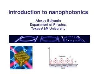
Nanophotonics-An Overview NSF-RISE Workshop July 9-14, 2007 Anup Sharma Department of Physics Alabama A&M University Anup.sharma@aamu.edu. What is Nanophotonics? Science of Light-Matter Interaction at Nanometer scale (< 1 micron to ≥ 1 nm). Examples of Nanophotonics.

E N D
Nanophotonics-An Overview NSF-RISE Workshop July 9-14, 2007 Anup Sharma Department of Physics Alabama A&M University Anup.sharma@aamu.edu
What is Nanophotonics?Science of Light-Matter Interaction at Nanometer scale (< 1 micron to ≥ 1 nm)
Examples of Nanophotonics • Iridescent colors on butterfly wings are due to Photonic-Crystals. i.e. Stacks of Nanoscale Gratings
Emission of Semiconductor (CdS, InAs, InP, CdSe) Nanospheres depends on the size Used for Bioimaging and Fabrication of Quantum-Well Lasers
Metal Nanoparticles Enhance Raman Scattering Signals by several orders of magnitude This Effect is called Surface Enhanced Raman Scattering (SERS)
Nanophotonics can be divided into three parts Example: Near-Field confinement of radiation by squeezing light through nanoscale apertures 1. Nanoscale confinement of Radiation Used for Near-Field Microscopy to resolve below the Far-Field Diffraction Limit. Also used for Near-Field Optical/UV Lithography.
2. Nanoscale confinement of Matter Nanoscale Cyrstals are used for: • (i) Optical Upconversion of radiation in Rare-Earth Nanocrystals. • (ii) Size-dependent Emission properties of nanoscale semiconductor crystals (Quantum dots or Q-dots) Metal nanoparticles and nanotips used in Surface Enhanced Raman Spectroscopy Photonic Bandgap Crystals and Photonic Bandgap Fibers (Photonic Fibers) involve periodic variation of dielectric constant over wavelength-scale. Applications: Fabrication of MOEMS (Micro Opto Electro Mechanical Systems), Micro-Optics, i.e. Microlasers, Directional Couplers between waveguides, Biophotonic Chips etc.
3. Nanoscale Photoprocesses Examples: Nanoscale Lithography, Fabrication of Nanoscale Structures, Nanoscale Optical Memories Foundations for Nanophotonics Basic Equations describing propagation of photons in dielectrics has some similarities to propagation of electrons in crystals Similarities between Photons and Electrons Wavelength of Light, Wavelength of Electrons,
Maxwell’s Equations for Light Eigenvalue Wave Equation: Describes the allowed frequencies of light Schrodinger’s Eigenvalue Equation for Electrons: Describes allowed Energies of Electrons
Free Space Solutions: Photon Plane Wave: Electron Plane Wave: Interaction Potential in a Medium: Propagation of Light affected by the Dielectric Medium (refractive index) Propagation of Electrons affected by Coulomb Potential
Propagation through Classically Forbidden Zones: Photon tunneling through classically forbidden zones. E and B fields decay exponentially. k-vector imaginary. Electron Wavefunction decays exponentially in forbidden zones
Confinement of Light and Electrons Confinement of Light results in field variations similar to the confinement of Electron in a Potential Well. For Light, the analogue of a Potential Well is a region of high refractive-index bounded by a region of lower refractive-index. Microscale Confinement of Light Nanoscale Confinement of Electrons
Differences between Light and Electron Waves: Electron Momentum generally bigger than photon momentum and so wavelength of light generally < 1 micron while wavelength of electrons generally < 1 nm. Light wave is described by a vector field described by E and B while electron wavefunction is scalar Photons satisfy Bose-Einstein statistics while Electrons are Fermions
Free-Space Propagation: • Free space propagation of both electrons and photons can be described by Plane Waves. • Momentum for both electrons and photons, p = (h/2π)k • For Photons, k = (2π/λ) while for Electrons, k = (2π/h)mv • For Photons, Energy E = pc =(h/2π)kc while for Electrons,
Electronic and Photonic Crystals Similar to the periodic electron-crystal lattice, one can fabricate photonic-crystal lattice. The refractive index varies with a much larger period of around 200 nm.
Nanoscale Optical Interactions Light propagating in a medium of high refractive index can be totally internally reflected at the interface with a lower refractive index. This involves interaction of light with matter over nanoscale distances. Some examples: Applications: Existence of an evanescent wave was first demonstrated by Newton. Light is transmitted not only at the point of contact but also through the neighboring regions due to penetration evanescent field through thin air film
Excitation of Surface Plasmon Resonance by Evanescent-Tail Surface plasmon is a wave at the interface of a metal and a dielectric film. This is a widely used technique for Biosensing and instruments using this technique are available commercially. To generate a Surface Plasma Wave, the diagram shown below is used. For Surface Plasma Wave traveling in z-direction, the condition to excite it optically is, reflected light intensity is seen. Thickness of metal film is 40-50 nm. By coating the dielectric film with biological antibodies, this is a widely used technique for sensing antigens, proteins etc. When the resonance condition is met, a sharp decrease of the internally
Nanoscale Confinement of Light: Near-Field Microscopy for Sub-Wavelength Resolution In Far-Field Microscopy, This can be overcome with Near-Field Techniques by having nanoscale apertures or by using aperture-less techniques which enhance light interaction over nanoscale dimensions with the use of nanoscale tips, nanospheres etc. The idea of using sub-wavelength aperture to improve optical resolution was first proposed by Synge in a letter to Einstein in 1928. These ideas were implemented into optics much later in 1972 [Ash and Nicholls] Schematic set-ups for Near-Field Scanning Optical Microscope (NSOM) Aperture-less Technique: Near-Field around Nano-Tip Near-field light decays over a distance of 50 nm from aperture. Tapered Optical-Fiber
Theoretical Results for Near-Field Nanoscopic Interactions Light Diffraction by Sub-Wavelength [(a / λ) < 1] Circular Aperture Only the terms with (1/r) contribute to net average radiation intensity when flux over a spherical surface is evaluated. Other terms give evanescent near-field radiation over distances less than (λ/2π).
Aperture-less Near-Field Microscopy Effect of Evanescent Coupling on radiative life-time of a dipole is shown below: In the aperture-less technique of microscopy, a metal tip of diameter < 50 nm is used to enhance inelastic scattering like Raman, fluorescence, nonlinear phenomena. For small distances between the tip and sample substrate (<50 nm), this enhancement is due to the near-field component of light diffracted by the tip. The radiative decay rate for the dipole is calculated as the dipole is translated along the x-axis for a fixed distance (D) between the two substrates. This is shown below. Limitation of small throughput of apertures can be overcome. Enhances inelastic light scattering from sample by generating surface plasma in the metals Above calculations clearly show that sub-wavelength resolution is due to coupling of the evanescent field to the environment. A. Rahmani et. al., Phys. Rev. A 56, 3245 (1997)
Nanoscale Confinement of Matter or Quantum-Confined Materials Quantum-confined materials refer to structures which are constrained to nanoscale lengths in one, two or all three dimensions. The length along which there is Quantum confinement must be small than de Broglie wavelength of electrons for thermal energies in the medium. Thermal Energy, E = de Broglie Wavelength, For T = 10 K, the calculated λ in GaAs is 162 nm for Electrons and 62 nm for Holes For effective Quantum-confinement, one or more dimensions must be less than 10 nm. Structures which are Quantum-confined show strong effect on their Optical Properties. Artificially created structures with Quantum-confinement on one, two or three dimensions are called, Quantum Wells, Quantum Wires and Quantum Dots respectively.
Z Quantum-Confined Materials Nanoscale Confinement in 1-Dimension results in a “Quantum Well” Quantization of energy into discrete levels has applications for fabrication of new solid-state lasers. Two or more Quantum wells side-by-side give rise to Multiple Quantum Wells (MQM) structure. Motion is confined only in the Z-direction. For electrons and holes moving in the Z-direction in low bandgap material, their motion can be described by Particle in a Box. If the depth of Potential Well is V, for energies E<V, we can write, At 300 K, The band gap of GaAs is 1.43 eV while it is 1.79 eV for AlxGa1-xAs (x=0.3). Thus the electrons and holes in GaAs are confined in a 1-D potential well of length L in the Z-direction. n = 1, 2, 3,…..
R 1-D Confinement: Quantum-Well Energy-levels Wave-functions in a Semi-conductor Quantum-Well Efficiency of a Quantum-Well Laser depends on the density of states First let us find the density of states in a bulk semiconductor: no confinement For electrons in conduction-band dN is proportional to This represents a sphere in momentum-space of radius R = (2mE)1/2 The number of states dN between energy E and E+dE is proportional to the volume of shell between R and R+dR Density, D(E)=dN / dE
Density of States for Quantum-Confinement Density of States Quantum Well: 1D Confinement Due to 1-D confinement, the number of continuous energy states in the 2-D phase space satisfy Quantum Wire: 2D Confinement 2D confinement in X and Z directions. For wires (e.g. of InP, CdSe). with rectangular cross-section, we can write: Quantum Dot: 3D Confinement For a cubical box with the discrete energy levels are given by:
Manifestations of new optical effects due to Quantum Confinement Size Dependence of Optical Properties In general, confinement produces a blue shift of the band-gap. Location of discrete energy levels depends on the size and nature of confinement. Increase of Oscillator Strengths This implies increase of optical transition probability. This happens anytime the energy levels are squeezed into a narrow range, resulting in an increase of energy density. The oscillator strengths increase as the confinement increases from Bulk to Quantum Well to Quantum Wire to Quantum Dot. New Intraband Transitions Confinement produces sub-bands within the conduction and valence bands, enabling intraband optical transitions which are not allowed in bulk. These IR transitions have applications to making new Quantum Cascade Lasers and also detectors. Oscillator strengths increase as the width of Quantum Well decreases.
Quantum Dots The most important optical feature of these structures is that absorption/emission spectra shifts to shorter wavelengths as the size becomes smaller. The luminescence spectra for InAs, InP and CdSe Quantum Dots is shown below. Likewise, Quantum-Dot Quantum Well refers to alternate layers of high and low bandgap semiconductors. Covering the surface of a Quantum Dot reduces non-radiative decay of electrons close to the surface and thus enhances luminescence intensity. Core-Shell Quantum Dot refers to a Quantum-Dot surrounded by a shell of higher band-gap semiconductor.
Quantum Confined Lasing Structures Semiconductor Laser is the best known application of quantum confined structures. Size of laser is around 100μm x 100μm x100μm and lasing wavelength can be tailored by the choice of the gain medium between 400 to 1600 nm. Single Quantum Well (SQW) lasers employ a much thinner (<10 nm) gain medium. Due to discrete energy levels, the threshold current for lasing is smaller, 0.5 mA as compared to 20 mA for double heterostructure laser (DHL). Line Widths are narrower, each mode can be < 10 MHz. It can be modulated at higher frequencies. First continuous wave semiconductor diode laser was a Double Heterostructure Laser. It was demonstrated by Alferov in USSR and by Panish and Hayashi in US. Thickness of GaAs was greater than 100 micron. So this is not a Quantum-Confined Laser Edge-Emitting Diode Laser
Quantum Cascade (QC) Laser Operates within the sub-bands of the Conduction band. It is different from other designs where emission is due to electron-hole recombination. Often called Unipolar Laser. In conventional semiconductor lasers one electron can emit only one photon as it combines with a hole. QC laser is a Multiple Quantum Well (MQW). Discovered in 1996 (Appl. Phy. Lett. 68, 3680). There could be ~50 Quantum Wells in MQW geometry. The barrier layer is very thin (1-3 nm)An excited electron emits 25-75 photons as it cascades down the ladder of sub-bands in the Conduction Band. QC lasers have been demonstrated for wavelengths between 3-20 micron. Useful for sensing atmospheric pollution
From Semi-Conductor Quantum-Dots to Metal Nano-Particles Under some conditions, one can resonantly excite a surface plasma-wave on the interface of metal and dielectric: Surface Plasmon Resonance (SPR). Applications of SPR has resulted in the field of Plasmonics Propagating SPR at Optical Frequency on a metal nano-wire: ‘Light on a Wire’ Science Daily(March 2005)Engineers Study Whether Plasmonics, 'Light On A Wire,' Is Circuitry Wave Of Future— If data drove itself around in cars, photonics would be a roomy minivan and electronics would be a nimble coupe. Photonic components such as fiber optic cables can carry a lot of data but are bulky compared to electronic circuits. Electronic components such as wires and transistors carry less data but can be incredibly small…..a single technology that has the capacity of photonics and the smallness of electronics would be the best bridge of all. A new research group in Stanford's School of Engineering is pioneering just such a technology: plasmonics…….. A new Journal called “plasmonics” published by Springer, beginning March 2006
Plasmonics Some Interesting Phenomena ● Interaction of light wave with metal nanoparticles ● Generation of surface plasma waves and dependence of plasmon resonance on metal particle size and geometry ● Dependence of plasmon resonance condition on the dielectric adjacent to the metal film and its application for sensing ● Enhancement of electromagnetic field close to metal nanoparticles and its application to spectroscopy like Surface Enhanced Raman and Fluorescence ● Application of metal nanotips for apertureless imaging ● Effects of metal nanoshells on plasmon resonance ● Propagation of high-frequency electromagnetic waves along sub-wavelength-wide metal waveguides ● Effect of metal surface on radiative decay of molecules
Generation of Surface Plasmons in a Bulk Metal Film Excitation of Surface Plasmon Wave Surface plasma waves can be generated optically on bulk surface at the interface of metal and dielectric. These are referred as Surface Plasmons. The traveling wave is associated with a wavevector k(sp). Special excitation geometry is required to produce such a wave. In nanoparticles, the surface plasmon wave is localized (not traveling) and so no special excitation geometry is required. For Surface Plasma Wave traveling in z-direction, the condition to excite it optically is, Wavelengths which are absorbed by metal nanoparticles and produce such a wave are called Surface Plasmon Bands or Plasmon Bands. Where, k(sp) is the wavevector of the surface plasma wave and k=(2π/λ) that of the light wave.
Surface Plasmon Resonance (SPR) on Metal Nano-Particles Most of the applications of such localized plasmon waves is due to electromagnetic field enhancement in the viscinity of the metal nanoparticle surface. Light absorption by nanoparticles takes place within a narrow range of wavelengths. This resonance (SPR) depends on size, shape and the nature of metal nanoparticle. This is shown in the graph below for gold nanoparticles. SPR can be understood from dielectric properties of metal nano-particles. This can be understood in a simple way from Drude’s Model for Dielectric Constant in Metals. Where m is electron mass and –e is its charge. Г is a damping constant and electric field Solution are of form,
SPR on Metal Nano-Particles This gives Where plasma frequency, Real part of Dielectric Constant Substituting in equation above, we get As can be seen from above, real part of ε(ω) can be negative for Polarization vector, P is Calculated Plasma Wavelength for Silver is 137 nm and for Copper 114 nm. Thus in the visible region, Re{ε(ω)} is negative. N is number density of electrons and χ is susceptibility.
SPR on Metal Nano-Particles Surface Plasmon Resonance takes place for frequency which satisfies: Constant Г (ε2) describes damping of electron motion. In bulk metals, this is largely due to electron-electron and electron-phonon scattering. However in metal nanoparticles, surface effects dominate since electron motion is constrained by the size of nanospheres. This damping is inversely proportional to the size of sphere. Thus the effect of size on plasmon resonance in metal nanospheres is contained in Г. Absorption of incident light by Metal Nanospheres embedded in a Dielectric is given the Extinction Coefficient: Where, λ is the wavelength of light, εh is the dielectric constant of surrounding medium, N is the number density of metal spheres and V its volume, ε1 and ε2 are the real and imaginary parts of the metal dielectric constant
SPR on Metal Nano-Shells Dielectric Core surrounded by Gold Shell Another type of nanosphere is dielectric sphere coated with a nanoshell of metals like gold. Core materials like AuS and silica of radius between 30-250 nm and shell thickness of 10-30 nm. Thinness of the shell results in a substantial red-shift of plasmon resonance. Effective dielectric constant of the dielectric medium with embedded nanoparticles is given by Here f is the volume fraction of nanoparticles, δ is the ratio of core volume to the volume of particle and εh, εs, εc are respectively the dielectric constants of the surrounding medium, the shell and the core. In general, as the thickness decreases, the resonance shifts to longer wavelength. This is due to increased electron scattering and an increase in the damping constant in metal dielectric constant. As seen from equations above, the condition for resonance is Re(εs) + 2εh = 0
SPR on Metal Nano-Shells In general, as the shell thickness decreases, the resonance shifts to longer wavelengths. Vial on the left has solid gold colloids. Others have colloids with metal nano-shells with decreasing thickness. Vial on left absorbs IR Fabrication of Metal Nanoshells For fabrication, the dielectric sphere is coated with a layer of amines which binds 1-2 nm gold colloids from suspension. This is followed by a chemical treatment with HAuCl4 in the presence of formaldehyde. This results in an additional layer of gold.
Applications of Plasmonics Metal nanoshells have several potential uses. It has been shown that a coating of these prevents photo-oxidation of polymer semiconducting devices if the resonance condition for nanoshells is at the wavelength of maximum photo-oxidation. Nanoshells thus act an an extinction filter Nanoshells have also been used for whole blood immunoassay. Nanoshells can be attached to antibodies as shown below. They form nanoshell dimers when they attach to the antigen resulting in a change of plasmon resonance condition. This can be monitored optically.
Applications of Plasmonics Plasmonic Wave Guiding Light on a Wire Waveguiding in traditional optical waveguides involves structures which cannot be smaller than λ/2. Further, waveguiding along bent guides is very lossy. The latter problem is overcome in photonic bandgap structures. But the dimensions of the structures are still limited by the wavelength of light. These surface excitations can be at any frequency between UV and IR and so these waveguides combine the less bulky nature of metal waveguides with the high bandwidth of optical waveguides. Typical size of metal nanosphere is 50 nm. Plasmon excitations can travel over bent plasmonic waveguides. A weakness of this technique is high loss (6 dB/μm) and transmission has been demonstrated over short (~ 1 μm) distances. It is an active area of research for future applications. The latter restriction can be overcome by waveguiding of plasmonic excitation in closely placed metal nanoparticles.
Applications of Plasmonics Electromagnetic field is enhanced locally on the surface of metal particles. This enhancement is especially strong at plasmon resonance. Surface Enhanced Raman Scattering (SERS) Aperture-Less Near-Field Microscopy Local field enhancement due to surface plasmons has been developed as a technique for aperture-less near-field microscopy. A nano-tip metal needle is used within the focal volume of an excitation laser.
Applications of Plasmonics Surface Plasmon-Wave Bio-Sensor Excitation of a plasmon wave at the interface between a metal and dielectric films has been used for sensing by evanescent wave spectroscopy. The evanescent wave associated with plasmon wave, penetrates the dielectric film to sense in the medium around. Evanescent wave can be absorbed by molecules being sensed. The technique shown above is for biosensing by antibodies. As they conjugate with specific antigens, the dielectric constant of the film changes and this is sensitively observed as an increase of internally reflected light since the condition for plasmon resonance is no longer met. This technique is widely used in several commercially available sensors.
1D Photonic Crystal: Stack of alternating refractive index material in Z direction Photonic Crystals In common “Electronic Crystals” like NaCl, the periodicity is ~ 1 nm. Photonic Crystals are produced by periodically varying refractive index in one, two or three dimensions. The period is comparable to the wavelength of light. Thus the field of Photonic Crystals can be looked upon as Microphotonics. However, in order to fabricate Photonic Crystals with micron-scale period, the fabrication technique must have nano-scale resolution. Thus it is appropriate to include Photonic Crystals in our study of Nanophotonics. Figures below show schematic representations of 1D, 2D and 3D Photonic Crystals. 2D Photonic Crystal: Periodic variation of refractive index in X and Y directions 3D Photonic Crystal: Periodic variation of refractive index in X, Y and Z directions
Photonic Crystals In Nature, parts of several living organisms have Photonic Crystals in them. Iridescent colors of butterfly wings and peacock feathers are due to Photonic Crystals. Photonic Band Gap crystals have several photonics-related applications, including microlasers, and waveguides/ waveguide-couplers, photonic band-gap optical fibers with novel dispersion characteristics etc.
Similarities between Electronic and Photonic Crystals The most striking similarity is the Band-Gap within the spectra of Electron and Photon Energies Likewise, diffraction of light within a Photonic Crystal is forbidden for a range of frequencies which gives the concept of Photonic Band-Gap.The forbidden range of frequencies depends on the direction of light with respect to the photonic crystal lattice. However, for a sufficiently refractive-index contrast (ratio n1/n2), there exists a Band-Gap which is omni-directional. Solution of Schroedinger’s equation in a 3D periodic coulomb potential for electron crystal forbids propagation of free electrons with energies within the Energy Band-Gap.
Band-Gap in Photonic Crystals Band-Gap frequencies when incident on the photonic crystal will be not be transmitted but be reflected/diffracted Optical characteristics of Photonic Crystals can best be understood by plotting the Dispersion Curve, i.e. variation of frequency (ω) of light with components of its wave-vector (k). Similar dispersion curves in Electronic Crystals, i.e. variation of energy E with k of electrons reveal the Electronic Band Gap. Period of refractive index variation in Photonic Crystals is taken as a. Figure shows dispersion character of light in a bulk medium with a uniform refractive index, n
Theoretical Modeling of Photonic Crystals Thus the incident and diffracted z-components of wave-vector are shifted with respect to each other by integral multiple of (2π/a). A special case of diffraction is Bragg Diffraction, when incident light is reflected by the photonic crystal 1D Photonic Crystal It is simplest to plot the dispersion curves for 1D Photonic Crystals. Incident light with a wave-vector (k) is diffracted by the 1D photonic crystal (period, a). Incident light can be diffracted into many possible directions as shown in the figure above. Wave-vectors are related by (show as Home-Work): Thus, whenever kz is a multiple of (π/a), the incident wave is reflected back. It cannot propagate in the photonic crystal and the group-velocity of such a wave is zero.
Dispersion in 1D Photonic Crystals Deviation from the straight-line dispersion curve of a uniform bulk medium is seen in the diagram. To ensure Bragg reflection for kz = ±N(π/a), the curve becomes horizontal. It is necessary to plot the above dispersion curve only for values of kz between –π/a and π/a. All other values of kz can be got by diffraction of waves with kz between –π/a and π/a. The region of kz between –π/a and π/a is called the First Brillouin Zone. There is a band of frequencies that are forbidden for all possible values of kz. This is the Band-Gap for the 1D Photonic Crystal.
2D Photonic Crystals Compared to 1D Photonic Crystal, it is relatively more difficult to deduce the Dispersion Curves for 2D and 3D Photonic Crystal. The software for doing this is publicly available at: http://www.elec.gla.ac.uk/groups/opto/photoniccrystal/Software/SoftwareMain.htm Dispersion curves for k for the boundary of the shaded region are plotted in three parts: In the first part (Г to M), k increases from 0 to ГM along the same direction. In the second part, the tip of k vector moves from M to K. In the third part (Г to K), k increases from 0 to ГK along the same direction. For sufficiently high ratio of refractive index (n1/n2), there exists a Band-Gap. Just like for 1D case, it is necessary only to investigate dispersion curves for values of k within the First Brillouin Zone.
Properties of Photonic Crystals Super Refraction or Super Prism Effect Prism effect is related to the derivative (dn/dλ) of refractive index with wavelength. This derivative can be made unusually large in photonic crystals. This can be understood with dispersion curves for 2D photonic crystals mentioned earlier. Prism effect refers to separation of colors by refraction through a prism. This is related to dispersion or variation of refractive index with wavelength. In a normal bulk medium like glass, dispersion is small. Photonic crystals can also exhibit an effective negative refractive index as explained below. This effect is seen in photonic crystals in the microwave and visible regions of spectrum.
Fabrication Techniques for Photonic Crystals Fabrication of 1D and 2D Photonic Crystals These are relatively easy to fabricate using UV and Electron-Beam Lithography. Bragg Grating in an optical fiber is a simple 1D Photonic Crystal. It is fabricated by UV Lithography Fabrication of 3D Photonic Crystals 1. Sedimentation of monodisperse colloidal nanospheres of polystyrene or silica. Fiber Bragg-Grating 2. Two-photon Lithography Since two-photon absorption takes place only close to the focal point of a laser, one can Holographic UV Lithography with 244 nm UV light fabricate structures deep within the volume of the polymer matrix. US Patent 6,873,762, awarded 2005
Applications of Photonic Crystals Photonic Components using 2D Photonic Crystals 2D Photonic crystals have a potential for fabricating waveguides and related components for integrated optics. Unlike the conventional refractive planar waveguides, these work by diffraction. Modes that cannot propagate through the 2D photonic crystal lattice (i.e. those within the band-gap) can propagate easily within the waveguides, including those waveguides which have a sharp bend at right angle. Microcavity Effect in 3D Photonic Crystals Defects in a Photonic Crystal Lattice produce microcavities which have size-dependent radiation modes. Just like electronic crystal these produce defect-states in the Band-Gap. Microcavity is resonant for wavelength λ, satisfying, D = N(λ/2), where N is an integer and D, the characteristic size of the cavity.Microcavity lasers have been fabricated by this technique.