Download
1 / 33
330 likes | 492 Views
Digital Circuits. A key element of electrical engineering sources: http://www.facstaff.bucknell.edu/mastascu/eLessonsHTML/EEIndex.html http://www.jhu.edu/~virtlab/logic/log_cir.htm. Foundations of Electrical Engineering. Electrophysics Maxwell's Equations, Circuit theory

E N D
Digital Circuits A key element of electrical engineering sources:http://www.facstaff.bucknell.edu/mastascu/eLessonsHTML/EEIndex.html http://www.jhu.edu/~virtlab/logic/log_cir.htm
Foundations of Electrical Engineering • Electrophysics • Maxwell's Equations, Circuit theory • Information (Communications) Theory • Data rate vs Signal Strength, Error correction • Digital Logic • Using Logic Gates to build up complex ccts 2
EE Subdisciplines • Power Systems • Electromagnetics • Solid State • Communication/Signal Processing • Controls • Analog/Digital Design 3
H2O Low Pressure High Pressure What is Voltage? V = “Electrical pressure” - measured involts. Figure 1.1
A battery in an electrical circuit plays the same role as a pump in a water system.
Where can I find a digital circuit? • Digital Circuits and Digital Logic are the buiding blocks for • computers • certain control systems (robots, factories) • LED displays • Digital Circuits are built up from Analog circuits • analog: continuous varying, digital: discrete steps • electricity has many characteristics of logic (+/-, True/False, etc)
Digital Logic is based on Binary • Two possible states • True/False • 1/0 • Yes/No • On/Off • Light/Dark
Logic Signals • Different systems for representing binary info in the physical world: • A voltage signal: • Zero (0) corresponding to 0 volts • One (1) corresponding to five volts. • A sinewave: • Zero corresponding to some frequency • One corresponding to some other frequency. • Switches: • OPEN for "0" and CLOSED for "1". • (And there are more ways!)
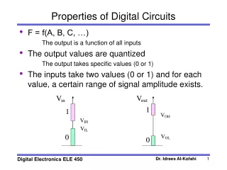
Characteristics of Logic Signals • Change in time • Initially we look at unchanging values • Voltage signal takes on two values • corresponding to 0 and 1. • for example, 0 Volts and 5 volts • We can associate a variable with a logic signal • assign a symbol to represent that variable • like the symbol A.
Think Binary! • Examples: • Cell phone converts voice into series of ones and zeros • Thermostat: 1 when temp is too low, 0 when too high • Logic signal, A, takes on values of 0 (FALSE, OFF) or 1 (TRUE, ON). • might be a voltage, a switch closure, etc. • More generally, think in terms of zeros and ones • not in terms of the values of the voltage or switches.
Operations on Logic Circuits • Suppose there are 2 logic signals. A and B • We often want to derive a 3rd signal C based on the values of A and B • if it is dark outside (A) OR raining (B) • Turn on lights (C) OR GATE
Logic Gates • Logic Gates are digital circuit packages that perform logic operations on logic signals • AND gate: both must be true for true output • OR gate: only one must be true for true output • NOT gate: true in means false out and vice versa • NAND gate: the opposite of AND • AND followed by NOT
Truth Tables and Logic Gates • Truth tables use 1/0 instead of True/False • OR AND NOT (inverter)
NAND GATE = NOT AND A B C • An AND gate • followed by NOT • Truth Table Usually drawn as: A B C Any logic gate can be builtfrom 1 or more NAND gates!
Lab: LS7400 Quad Nand Gate IC • Pinout shows which pins are connected to what • Vcc = +5 V, -Vcc = 0V • Verify the notch location!!
Breadboard a NAND gate • a breadboard is a quick way to build circuits without soldering • 5 pin rows are connected by metal clips • vertical column on sides are connected.
Connect Power Supply to Breadboard Ground+5V Black to GroundRed to +5V
Add LEDs to show value of A,B(1- 470 Ohm Resistor for each LED) The shorter Wire on LED goes to GROUND When both are connected, turn on power (A, B are '1')
Move brown wire to change B to '0' Add LED to output pin 3
A NAND Inverter • Connecting the two inputs • A and B are both at A • Truth table is the same as Inverter A C
NAND + NAND = AND • Taking NOT-NOT AND A B C Try it! Add wires from Pin 3 to 4, 4 to 5 move your output Resistor to pin 6
FLIP FLOP – another 2 NAND cct • Output of 1 (P) • feeds back to input of 2 • Output of 2 (Q) • feeds back to input of 1 MEMORY!! previous state was X=1, Y=0 previous state was X=0, Y=1
Flip Flop Wiring And each labelled pin A,B,P,Q have resistors and LED to ground for monitoring
Flip Flop in Action A=0 B=1 A=0 B=0
Flip Flop in Action A=0 B=1 A=1, B=1 A=1 B=0 A=1, B=1
3 NANDs make an OR A C B Use the digital circuit simulator to try out:http://www.jhu.edu/~virtlab/logic/logic.htm
Team Challenges (simulate or wire up) Using only NAND gates: A . Design, construct and test a three input AND. B. Design, construct and test a three input NAND. C. Design a four input NAND. Hint: If wiring, use an LED indicator to show the inputs and/or the outputs in your circuits. Use a current-limiting resistor for each LED.
Use the circuit builderhttp://www.jhu.edu/~virtlab/logic/logic.htm D. Using only AND, NOT, and OR produce a three-input OR circuit, ie., the output is 1 if any of the inputs is 1. E. Create a two-input "adder" with two outputs: the one-digit result of the add, and the value of a "carry" bit. In binary arithmetic, 1+1=0 with a carry=1.
Super Bowl Problem • At the beginning of halftime during the Superbowl, • 35 million toilets are flushed almost simultaneously. • Resulting loss of water pressure wreaks havoc on many municipal water systems. • Make a controller to solve the problem for a "three toilet" system. • Devise a logic circuit whose "1" inputs represent "flushes" • and whose "1" outputs represent opened water valves • If no more than one toilet is flushed, then that toilet's water valve opens, • the others remaining closed. • If more than one toilet is flushed, then all the water valves remain closed.