Download
1 / 19
190 likes | 207 Views
https://gioumeh.com/product/mechanics-of-materials-solution/<br>------------------------------------------------------------<br>Authors: Russell C. Hibbeler<br> Published: Pearson 2017 , Pearson 2018 , Pearson 2013<br> Edition: 10th , 10th Global edition , 9th edition<br> Pages: 1600 , 1583 , 1598<br> Type: pdf<br> Size: 155 MB , 160 MB , 87 MB<br> Content: 9th & 10th edition 10th SI edition solutions<br> Sample: 9th sample file<br> Sample: 10th sample file<br> Sample: 10th SI sample file <br> Download After Payment

E N D
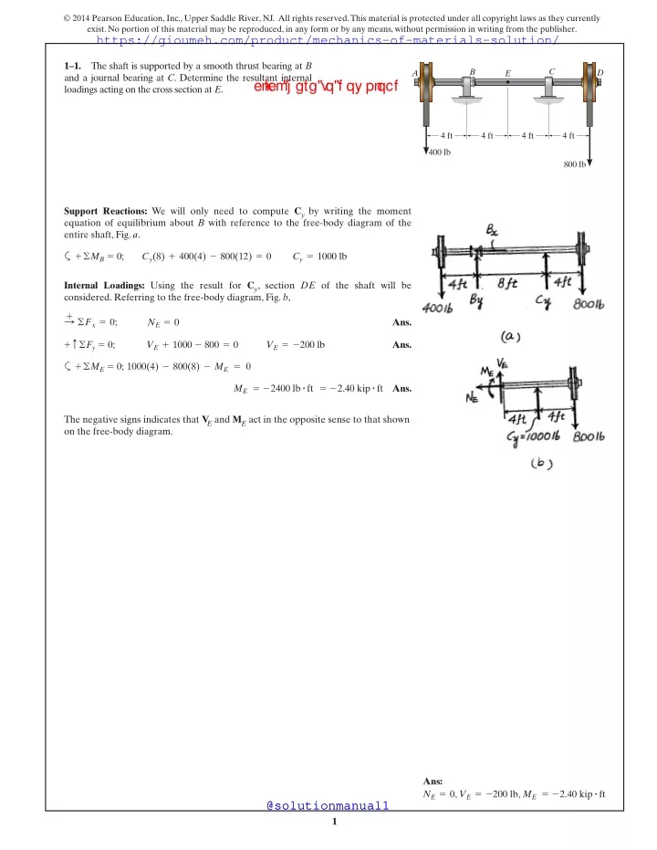
© 2014 Pearson Education,Inc.,Upper Saddle River,NJ. All rights reserved.This material is protected under all copyright laws as they currently exist.No portion of this material may be reproduced,in any form or by any means,without permission in writing from the publisher. https://gioumeh.com/product/mechanics-of-materials-solution/ 1–1. and a journal bearing at C. Determine the resultant internal loadings acting on the cross section at E. The shaft is supported by a smooth thrust bearing at B C B D A E cl i ck h ere t o d ow nl oad 4 ft 4 ft 4 ft 4 ft 400 lb 800 lb Support Reactions: We will only need to compute Cyby writing the moment equation of equilibrium about B with reference to the free-body diagram of the entire shaft,Fig.a. +©MB= 0; Cy(8) + 400(4) - 800(12) = 0 Cy= 1000 lb a Internal Loadings: Using the result for Cy, section DE of the shaft will be considered.Referring to the free-body diagram,Fig.b, : +©Fx= 0; Ans. NE= 0 +c©Fy= 0; Ans. VE+ 1000 - 800 = 0 VE= -200 lb +©ME= 0; 1000(4) - 800(8) - ME=0 a ME= -2400 lb#ft = -2.40 kip#ft Ans. The negative signs indicates that VEand MEact in the opposite sense to that shown on the free-body diagram. Ans: NE= 0 , ME= -2.40 kip#ft VE= -200 lb , @solutionmanual1 @solutionmanual1 1
© 2014 Pearson Education,Inc.,Upper Saddle River,NJ. All rights reserved.This material is protected under all copyright laws as they currently exist.No portion of this material may be reproduced,in any form or by any means,without permission in writing from the publisher. https://gioumeh.com/product/mechanics-of-materials-solution/ 1–2. force in the member at (a) section a–a and (b) section b–b, each of which passes through point A. The 500-lb load is applied along the centroidal axis of the member. Determine the resultant internal normal and shear a b 30? cl i ck h ere t o d ow nl oad 500 lb 500 lb A b a (a) : +©Fx= 0; Na- 500 = 0 Na= 500 lb Ans. Ans. +T©Fy= 0; Va= 0 (b) R+©Fx= 0; Nb- 500 cos 30° = 0 Ans. Nb= 433 lb +Q©Fy= 0; Vb- 500 sin 30° = 0 Ans. Vb= 250 lb Ans: Na= 500 lb Va= 0 , , Nb= 433 lb, Vb= 250 lb @solutionmanual1 @solutionmanual1 2
© 2014 Pearson Education,Inc.,Upper Saddle River,NJ. All rights reserved.This material is protected under all copyright laws as they currently exist.No portion of this material may be reproduced,in any form or by any means,without permission in writing from the publisher. https://gioumeh.com/product/mechanics-of-materials-solution/ > 1–3. weight of 80 lb ft. If the trolley supports a load of 1500 lb, determine the resultant internal loadings acting on the cross sections through points C and D. The beam AB is fixed to the wall and has a uniform 20 ft 10 ft 5 ft 3 ft cl i ck h ere t o d ow nl oad A B C D 1500 lb Segment BC: ; +©Fx= 0; Ans. NC= 0 +c©Fy= 0; VC- 2.0 - 1.5 = 0 Ans. VC= 3.50 kip +©MC= 0; -MC- 2(12.5) - 1.5 (15) = 0 a MC= -47.5 kip#ft Ans. Segment BD: ; +©Fx= 0; Ans. ND= 0 +c©Fy= 0; VD- 0.24 = 0 Ans. VD= 0.240 kip +©MD= 0; -MD- 0.24 (1.5) = 0 a MD= -0.360 kip#ft Ans. Ans: NC= 0 MC= -47.5 kip#ft, VC= 3.50 kip , , , , MD= -0.360 kip#ft ND= 0 VD= 0.240 kip @solutionmanual1 @solutionmanual1 3
© 2014 Pearson Education,Inc.,Upper Saddle River,NJ. All rights reserved.This material is protected under all copyright laws as they currently exist.No portion of this material may be reproduced,in any form or by any means,without permission in writing from the publisher. https://gioumeh.com/product/mechanics-of-materials-solution/ *1–4. and a smooth journal bearing at B. Determine the resultant internal loadings acting on the cross section at C. The shaft is supported by a smooth thrust bearing at A 600 N/m cl i ck h ere t o d ow nl oad D A B C 1 m 1 m 1 m 1.5 m 1.5 m 900 N Support Reactions: We will only need to compute Byby writing the moment equation of equilibrium about A with reference to the free-body diagram of the entire shaft,Fig. a. +©MA= 0; By(4.5) - 600(2)(2) - 900(6) = 0 By= 1733.33 N a Internal Loadings: Using the result of By, section CD of the shaft will be considered. Referring to the free-body diagram of this part, Fig. b, ; +©Fx= 0; Ans. NC= 0 +c©Fy= 0; Ans. VC- 600(1) + 1733.33 - 900 = 0 VC= -233 N +©MC= 0; 1733.33(2.5) - 600(1)(0.5) - 900(4) - MC= 0 a MC= 433 N#m Ans. The negative sign indicates that VCact in the opposite sense to that shown on the free-body diagram. @solutionmanual1 @solutionmanual1 4
© 2014 Pearson Education,Inc.,Upper Saddle River,NJ. All rights reserved.This material is protected under all copyright laws as they currently exist.No portion of this material may be reproduced,in any form or by any means,without permission in writing from the publisher. https://gioumeh.com/product/mechanics-of-materials-solution/ 1–5. beam at cross sections through points D and E. Point E is just to the right of the 3-kip load. Determine the resultant internal loadings in the 3 kip cl i ck h ere t o d ow nl oad 1.5 kip/ft A C D E B 4 ft 4 ft 6 ft 6 ft +©MB= 0;9.00(4) - Ay(12) = 0Ay= 3.00 kip Support Reactions: For member AB +©Fx= 0;Bx= 0 a : +c©Fy= 0;By+ 3.00 - 9.00 = 0By= 6.00 kip ©Fx= 0;ND= 0 Equations of Equilibrium: For point D +c©Fy= 0;3.00 - 2.25 - VD= 0 : + Ans. +©MD= 0;MD+ 2.25(2) - 3.00(6) = 0 Ans. VD= 0.750 kip a MD= 13.5 kip#ft Ans. +©Fx= 0;NE= 0 Equations of Equilibrium: For point E +c©Fy= 0;-6.00 - 3 - VE= 0 : Ans. +©ME= 0;ME+ 6.00(4) = 0 Ans. VE= -9.00 kip a ME= -24.0 kip#ft Ans. Negative signs indicate that MEand VEact in the opposite direction to that shown on FBD. Ans: ND= 0 MD= 13.5 kip#ft, VD= 0.750 kip , , , , ME= -24.0 kip#ft NE= 0 VE= -9.00 kip @solutionmanual1 @solutionmanual1 5
© 2014 Pearson Education,Inc.,Upper Saddle River,NJ. All rights reserved.This material is protected under all copyright laws as they currently exist.No portion of this material may be reproduced,in any form or by any means,without permission in writing from the publisher. https://gioumeh.com/product/mechanics-of-materials-solution/ 1–6. moment at a section through point C. Take P = 8 kN. Determine the normal force, shear force, and B cl i ck h ere t o d ow nl oad 0.1 m 0.5 m C A 0.75 m 0.75 m 0.75 m P +©MA= 0;8(2.25) - T(0.6) = 0T = 30.0 kN Support Reactions: +©Fx= 0;30.0 - Ax= 0Ax= 30.0 kN a : +c©Fy= 0;Ay- 8 = 0Ay= 8.00 kN +©Fx= 0;-NC- 30.0 = 0 Equations of Equilibrium: For point C : +c©Fy= 0;VC+ 8.00 = 0 Ans. NC= -30.0 kN VC= -8.00 kN +©MC= 0;8.00(0.75) - MC= 0 Ans. MC= 6.00 kN#m a Ans. Negative signs indicate that NCand VCact in the opposite direction to that shown on FBD. Ans: NC= -30.0 kN, VC= -8.00 kN, MC= 6.00 kN#m @solutionmanual1 @solutionmanual1 6
© 2014 Pearson Education,Inc.,Upper Saddle River,NJ. All rights reserved.This material is protected under all copyright laws as they currently exist.No portion of this material may be reproduced,in any form or by any means,without permission in writing from the publisher. https://gioumeh.com/product/mechanics-of-materials-solution/ 1–7. Determine the largest vertical load P the frame will support and calculate the internal normal force, shear force, and moment at the cross section through point C for this loading. The cable will fail when subjected to a tension of 2 kN. B cl i ck h ere t o d ow nl oad 0.1 m 0.5 m C A 0.75 m 0.75 m 0.75 m P +©MA= 0;P(2.25) - 2(0.6) = 0 Support Reactions: a +©Fx= 0;2 - Ax= 0Ax= 2.00 kN Ans. P = 0.5333 kN = 0.533 kN : +c©Fy= 0;Ay- 0.5333 = 0Ay= 0.5333 kN +©Fx= 0;-NC- 2.00 = 0 Equations of Equilibrium: For point C : +c©Fy= 0;VC+ 0.5333 = 0 Ans. NC= -2.00 kN VC= -0.533 kN +©MC= 0;0.5333(0.75) - MC= 0 Ans. MC= 0.400 kN#m a Ans. Negative signs indicate that NCand VCact in the opposite direction to that shown on FBD. Ans: P = 0.533 kN NC= -2.00 kN VC= -0.533 kN , , , MC= 0.400 kN#m @solutionmanual1 @solutionmanual1 7
© 2014 Pearson Education,Inc.,Upper Saddle River,NJ. All rights reserved.This material is protected under all copyright laws as they currently exist.No portion of this material may be reproduced,in any form or by any means,without permission in writing from the publisher. https://gioumeh.com/product/mechanics-of-materials-solution/ *1–8. cross section through point C. Assume the reactions at the supports A and B are vertical. Determine the resultant internal loadings on the 6 kN 3 kN/m cl i ck h ere t o d ow nl oad B +©MB= 0;-Ay(4) + 6(3.5) +1 2 (3)(3)(2) = 0Ay= 7.50 kN A Referring to the FBD of the entire beam,Fig.a, C D 1.5 m 1.5 m a 0.5 m 0.5 m +©Fx= 0;NC= 0 Referring to the FBD of this segment,Fig.b, +c©Fy= 0;7.50 - 6 - VC= 0VC= 1.50 kN : Ans. +©MC= 0;MC+ 6(0.5) - 7.5(1) = 0MC= 4.50 kN#m Ans. Ans. a @solutionmanual1 @solutionmanual1 8
© 2014 Pearson Education,Inc.,Upper Saddle River,NJ. All rights reserved.This material is protected under all copyright laws as they currently exist.No portion of this material may be reproduced,in any form or by any means,without permission in writing from the publisher. https://gioumeh.com/product/mechanics-of-materials-solution/ 1–9. cross section through point D.Assume the reactions at the supports A and B are vertical. Determine the resultant internal loadings on the 6 kN 3 kN/m cl i ck h ere t o d ow nl oad B A C D 1.5 m 1.5 m 0.5 m 0.5 m Referring to the FBD of the entire beam,Fig.a, +©MA= 0;By(4) - 6(0.5) -1 2 (3)(3)(2) = 0By= 3.00 kN a +©Fx= 0;ND= 0 Referring to the FBD of this segment,Fig.b, : Ans. +c©Fy= 0;VD-1 2 (1.5)(1.5) + 3.00 = 0VD= -1.875 kN Ans. 2 (1.5)(1.5)(0.5) - MD= 0MD= 3.9375 kN#m +©MD= 0;3.00(1.5) -1 a = 3.94 kN#m Ans. Ans: ND= 0, VD= -1.875 kN, MD= 3.94 kN#m @solutionmanual1 @solutionmanual1 9
© 2014 Pearson Education,Inc.,Upper Saddle River,NJ. All rights reserved.This material is protected under all copyright laws as they currently exist.No portion of this material may be reproduced,in any form or by any means,without permission in writing from the publisher. https://gioumeh.com/product/mechanics-of-materials-solution/ > 1–10. have a uniform weight of 50 lb ft. If the hoist and load weigh 300 lb, determine the resultant internal loadings in the crane on cross sections through points A,B,and C. The boom DF of the jib crane and the column DE D F A B cl i ck h ere t o d ow nl oad 2 ft 8 ft 3 ft 5 ft C 300 lb 7 ft E +©Fx= 0;NA= 0 Equations of Equilibrium: For point A +c©Fy= 0;VA- 150 - 300 = 0 ; Ans. +©MA= 0;-MA- 150(1.5) - 300(3) = 0 Ans. VA= 450 lb a MA= -1125 lb#ft = -1.125 kip#ft Ans. Negative sign indicates that MAacts in the opposite direction to that shown on FBD. +©Fx= 0;NB= 0 Equations of Equilibrium: For point B +c©Fy= 0;VB- 550 - 300 = 0 ; Ans. +©MB= 0;-MB- 550(5.5) - 300(11) = 0 Ans. VB= 850 lb a MB= -6325 lb#ft = -6.325 kip#ft Ans. Negative sign indicates that MBacts in the opposite direction to that shown on FBD. +©Fx= 0;VC= 0 Equations of Equilibrium: For point C +c©Fy= 0;-NC- 250 - 650 - 300 = 0 ; Ans. +©MC= 0;-MC- 650(6.5) - 300(13) = 0 Ans. NC= -1200 lb = -1.20 kip a MC= -8125 lb#ft = -8.125 kip#ft Ans. Negative signs indicate that NCand MCact in the opposite direction to that shown on FBD. Ans: NA= 0 MA= -1.125 kip#ft, VA= 450 lb , , , , , MB= -6.325 kip#ft, NB= 0 VB= 850 lb MC= -8.125 kip#ft NC= -1.20 kip, VC= 0 @solutionmanual1 @solutionmanual1 10
© 2014 Pearson Education,Inc.,Upper Saddle River,NJ. All rights reserved.This material is protected under all copyright laws as they currently exist.No portion of this material may be reproduced,in any form or by any means,without permission in writing from the publisher. https://gioumeh.com/product/mechanics-of-materials-solution/ 1–11. can be assumed as a pin support, determine the resultant internal loadings acting on the cross section of the bone of the forearm at E.The biceps pulls on the bone along BD. The forearm and biceps support the 2-kg load at A.If C D cl i ck h ere t o d ow nl oad 75? A CE B Support Reactions: In this case, all the support reactions will be completed. Referring to the free-body diagram of the forearm,Fig.a, 230 mm 35 mm 35 mm +©MC= 0; FBD sin 75°(0.07) - 2(9.81)(0.3) = 0 FBD= 87.05 N a : +©Fx= 0; Cx- 87.05 cos 75° = 0 Cx= 22.53 N +c©Fy= 0; 87.05 sin 75° - 2(9.81) - Cy= 0 Cy= 64.47 N Internal Loadings: Using the results of Cxand Cy, section CE of the forearm will be considered.Referring to the free-body diagram of this part shown in Fig.b, : +©Fx= 0; NE+ 22.53 = 0 NE= -22.5 N Ans. +c©Fy= 0; -VE-64.47 = 0 VE= - 64.5 N Ans. ME= - 2.26 N#m Ans. +©ME= 0; ME+ 64.47(0.035) = 0 a The negative signs indicate that NE, VEand MEact in the opposite sense to that shown on the free-body diagram. Ans: NE= -22.5 N , ME= - 2.26 N#m VE= - 64.5 N , @solutionmanual1 @solutionmanual1 11
© 2014 Pearson Education,Inc.,Upper Saddle River,NJ. All rights reserved.This material is protected under all copyright laws as they currently exist.No portion of this material may be reproduced,in any form or by any means,without permission in writing from the publisher. https://gioumeh.com/product/mechanics-of-materials-solution/ *1–12. on each side by an arm.The tray is pin connected to the arm at A, and at B there is a smooth pin. (The pin can move within the slot in the arms to permit folding the tray against the front passenger seat when not in use.) Determine the resultant internal loadings acting on the cross section of the arm through point C when the tray arm supports the loads shown. The serving tray T used on an airplane is supported 12 N 9 N cl i ck h ere t o d ow nl oad 15 mm 100 mm 150 mm A B T 60? 500 mm VC MC C NC Ans. NC+ 9 cos 30° + 12 cos 30° = 0; NC= - 18.2 N b+©Fx= 0; a+©Fy= 0; Ans. VC- 9 sin 30° - 12 sin 30° = 0; VC= 10.5 N +©MC= 0; -MC- 9(0.5 cos 60° + 0.115) - 12(0.5 cos 60° + 0.265) = 0 a MC= - 9.46 N # m Ans. @solutionmanual1 @solutionmanual1 12
© 2014 Pearson Education,Inc.,Upper Saddle River,NJ. All rights reserved.This material is protected under all copyright laws as they currently exist.No portion of this material may be reproduced,in any form or by any means,without permission in writing from the publisher. https://gioumeh.com/product/mechanics-of-materials-solution/ 1–13. pretension force of internal loadings acting on section a–a that passes through point D. The blade of the hacksaw is subjected to a F = 100 N. a Determine the resultant cl i ck h ere t o d ow nl oad 225 mm b 30? B A D 150 mm b a F F C Internal Loadings: Referring to the free-body diagram of the section of the hacksaw shown in Fig.a, ; +©Fx= 0; Ans. Na-a+ 100 = 0 Na-a= -100 N +c©Fy= 0; Ans. Va-a= 0 Ma-a= -15 N # m Ans. +©MD= 0; -Ma-a- 100(0.15) = 0 a The negative sign indicates that Na–aand Ma–aact in the opposite sense to that shown on the free-body diagram. Ans: Na-a= -100 N , Ma-a= -15 N#m Va-a= 0 , @solutionmanual1 @solutionmanual1 13
© 2014 Pearson Education,Inc.,Upper Saddle River,NJ. All rights reserved.This material is protected under all copyright laws as they currently exist.No portion of this material may be reproduced,in any form or by any means,without permission in writing from the publisher. https://gioumeh.com/product/mechanics-of-materials-solution/ 1–14. pretension force of internal loadings acting on section b–b that passes through point D. The blade of the hacksaw is subjected to a . Determine the resultant F = 100 N a 225 mm cl i ck h ere t o d ow nl oad b 30? B A D 150 mm b a F F C Internal Loadings:Referring to the free-body diagram of the section of the hacksaw shown in Fig.a, Ans. ©Fx¿= 0; Nb-b+ 100 cos 30° = 0 Nb-b= -86.6 N Ans. ©Fy¿= 0; Vb-b- 100 sin 30° = 0 Vb-b= 50 N Mb-b= -15 N # m Ans. +©MD= 0; -Mb-b- 100(0.15) = 0 a The negative sign indicates that Nb–band Mb–b act in the opposite sense to that shown on the free-body diagram. Ans: Nb-b= -86.6 N Vb-b= 50 N , , Mb-b= -15 N#m @solutionmanual1 @solutionmanual1 14
© 2014 Pearson Education,Inc.,Upper Saddle River,NJ. All rights reserved.This material is protected under all copyright laws as they currently exist.No portion of this material may be reproduced,in any form or by any means,without permission in writing from the publisher. https://gioumeh.com/product/mechanics-of-materials-solution/ 1–15. wooden frame. Determine the resultant internal loadings on the cross section at D. A 150-lb bucket is suspended from a cable on the 1 ft 1 ft 2 ft cl i ck h ere t o d ow nl oad B D H C 2 ft 30? G 1 ft E 3 ft Support Reactions: We will only need to compute Bx,By,and FGH .Referring to the free-body diagram of member BC, Fig.a, I A + ©MB= 0: FGH sin 45°(2) - 150(4) = 0 FGH= 424.26 lb a : +©Fx= 0; 424.26 cos 45° - Bx= 0 Bx= 300 lb +c©Fy= 0; 424.26 sin 45° - 150 - By= 0 By= 150 lb Internal Loadings: Using the results of Bxand By,section BD of member BC will be considered.Referring to the free-body diagram of this part shown in Fig.b, : +©Fx= 0; Ans. ND- 300 = 0 ND= 300 lb +c©Fy= 0; Ans. - VD- 150 = 0 VD= -150 lb MD= - 150 lb # ft Ans. +©MD= 0; 150(1) + MD= 0 a The negative signs indicates that VDand MDact in the opposite sense to that shown on the free-body diagram. Ans: ND= 300 lb , MD= - 150 lb#ft VD= -150 lb , @solutionmanual1 @solutionmanual1 15
© 2014 Pearson Education,Inc.,Upper Saddle River,NJ. All rights reserved.This material is protected under all copyright laws as they currently exist.No portion of this material may be reproduced,in any form or by any means,without permission in writing from the publisher. https://gioumeh.com/product/mechanics-of-materials-solution/ *1–16. wooden frame. Determine the resultant internal loadings acting on the cross section at E. A 150-lb bucket is suspended from a cable on the 1 ft 1 ft 2 ft cl i ck h ere t o d ow nl oad B D H C 2 ft 30? G 1 ft E 3 ft Support Reactions: We will only need to compute Ax, Ay, and FBI. Referring to the free-body diagram of the frame,Fig.a, I A + ©MA= 0; FBIsin 30°(6) - 150(4) = 0 FBI=200 lb a : +©Fx= 0; Ax-200 sin 30° = 0 Ax=100 lb +c©Fy= 0; Ay- 200 cos 30° - 150 = 0 Ay=323.21 lb Internal Loadings: Using the results of Axand Ay,section AE of member AB will be considered.Referring to the free-body diagram of this part shown in Fig.b, : +©Fx= 0; Ans. NE+ 323.21 = 0 NE= - 323 lb +c©Fy= 0; Ans. 100 - VE= 0 VE= 100 lb ME= 300 lb # ft Ans. +©MD= 0; 100(3) - ME= 0 a The negative sign indicates that NEacts in the opposite sense to that shown on the free-body diagram. @solutionmanual1 @solutionmanual1 16
© 2014 Pearson Education,Inc.,Upper Saddle River,NJ. All rights reserved.This material is protected under all copyright laws as they currently exist.No portion of this material may be reproduced,in any form or by any means,without permission in writing from the publisher. https://gioumeh.com/product/mechanics-of-materials-solution/ 1–17. section a–a and section b–b. Each section passes through the centerline at point C. Determine resultant internal loadings acting on 5 kN B cl i ck h ere t o d ow nl oad b +©MA= 0;NB sin 45°(6) - 5(4.5) = 0NB= 5.303 kN a Referring to the FBD of the entire beam,Fig.a, 1.5 m a C 1.5 m +b©Fx¿= 0;Na-a+ 5.303 cos 45° = 0Na-a= -3.75 kN Referring to the FBD of this segment (section a–a),Fig.b, +a©Fy¿= 0;Va-a+ 5.303 sin 45° - 5 = 0Va-a= 1.25 kN 45? a b Ans. 45? A 3 m Ans. +©MC= 0;5.303 sin 45°(3) - 5(1.5) - Ma-a= 0Ma-a= 3.75 kN#m Ans. a +©Fx= 0;Nb-b- 5 cos 45° + 5.303 = 0Nb-b= -1.768 kN Referring to the FBD (section b–b) in Fig.c, ; +c©Fy= 0;Vb-b- 5 sin 45° = 0Vb-b= 3.536 kN = 3.54 kN Ans. = -1.77 kN +©MC= 0;5.303 sin 45° (3) - 5(1.5) - Mb-b= 0 Ans. a Mb-b= 3.75 kN#m Ans. Ans: Na-a= -3.75 kN, Va-a= 1.25 kN, Ma-a= 3.75 kN#m, Nb-b= -1.77 kN, Vb-b= 3.54 kN#m, Mb-b= 3.75 kN#m @solutionmanual1 @solutionmanual1 17
© 2014 Pearson Education,Inc.,Upper Saddle River,NJ. All rights reserved.This material is protected under all copyright laws as they currently exist.No portion of this material may be reproduced,in any form or by any means,without permission in writing from the publisher. https://gioumeh.com/product/mechanics-of-materials-solution/ 1–18. Determine the resultant internal loadings acting on the cross section at point C. The bolt shank is subjected to a tension of 80 lb. cl i ck h ere t o d ow nl oad C 6 in. 90? A B +©Fx= 0;NC+ 80 = 0;NC= -80 lb Segment AC: +c©Fy= 0;VC= 0 : Ans. +©MC= 0;MC+ 80(6) = 0;MC= -480 lb#in. Ans. Ans. a Ans: NC= -80 lb, MC= -480 lb#in. VC= 0, @solutionmanual1 @solutionmanual1 18
© 2014 Pearson Education,Inc.,Upper Saddle River,NJ. All rights reserved.This material is protected under all copyright laws as they currently exist.No portion of this material may be reproduced,in any form or by any means,without permission in writing from the publisher. https://gioumeh.com/product/mechanics-of-materials-solution/ 1–19. the cross section through point C. Assume the reactions at the supports A and B are vertical. Determine the resultant internal loadings acting on 6 kip/ft 6 kip/ft cl i ck h ere t o d ow nl oad A B C D 3 ft 3 ft 6 ft Referring to the FBD of the entire beam,Fig.a, + ©MB= 0;1 2 (6)(6)(2) +1 2 (6)(6)(10) - Ay(12) = 0Ay= 18.0 kip a +©Fx= 0;NC= 0 Referring to the FBD of this segment,Fig.b, : Ans. +c©Fy= 0;18.0 -1 2 (3)(3) - (3)(3) - VC= 0VC= 4.50 kip Ans. +©MC= 0;MC+ (3)(3)(1.5) +1 2 (3)(3)(2) - 18.0(3) = 0 a MC= 31.5 kip#ft Ans. Ans: NC= 0 , MC= 31.5 kip#ft VC= 4.50 kip , @solutionmanual1 @solutionmanual1 19